
—


MOTOR GUIDE | JULY 2019
Low voltage motors Motor guide
2 LOW VOLTAGE MOTORS MOTOR GUIDE JULY 2019

—
We provide motors and generators, services andexpertise to save energy andimprove customers’ processesover the total lifecycle or ourproducts, and beyond.
Motor guide – basic technical informationabout low voltage standard motors
© Copyright 2019 ABB. All rights reserved. Specifications subject to change without notice.
ISBN 952-91-0728-5Fourth edition 2019
—
Table of contents
006 1. Introduction 007 1.1 About ABB
007 1.1.1. Electrification Products007 1.1.2. Robotics and Motion007 1.1.3. Industrial Automation008 1.1.4. Power Grids
008 1.2 IEC low voltage motor ranges008 1.2.1 Standard induction motors
008 1.2.2 Motors for explosive atmospheres009 1.2.3 Frequency-controlled motors
009 1.2.4 Motors for industries and specific applications
010 2. International motor efficiency011 2.1 Standards and regulations011 2.1.1 Minimum energy performance standards012 2.1.2 IEC 60034-30-1:2014
013 2.1.3 ABB and efficiency standards015 2.2 Life cycle approach and energy appraisal015 2.2.1 Energy appraisal
016 2.3 Environmental management within ABB016 2.3.1 ISO 14001
016 2.3.2 Hazardous substances 016 2.3.3 Materials selection
017 2.3.4 EU Directive 2012/19/EU (WEEE)
018 3. Standards 019 3.1 Definitions
020 3.2 Standards tables
020 3.2.1 The main standards for low voltage motors021 3.2.2 The main EU directives for motors021 3.2.3 Efficiency determination for motors outside Europe022 3.3 Direction of rotation
023 3.4 Cooling
024 3.5 Degrees of protection: IP code/IK code025 3.6 Standard voltage ranges026 3.7 Voltage and frequency026 3.8 Tolerance
027 3.9 Mounting arrangements028 3.10 Dimensions
030 3.11 Output power and frame size ratio
4 LOW VOLTAGE MOTORS MOTOR GUIDE JULY 2019
032 4. Electrical design – induction motors033 4.1 The induction motor034 4.2 Insulation 035 4.3 Thermistors
035 4.4 Ambient temperatures and high altitudes036 4.5 Starting methods
036 4.5.1 Direct-on-line (DOL) starting036 4.5.2 Star-delta starting
037 4.5.3 Soft starters
038 4.5.4 Starting with a variable speed drive039 4.6 Starting limitations046 4.7 Duty types 050 4.8 Uprating
051 4.9 Efficiency and types of losses052 4.10 Power factor
055 4.11 Air flow and air speed056 4.12 Connection diagram
058 5. Mechanical design059 5.1 Motor construction060 5.2 Frame constructions061 5.3 Terminal boxes 063 5.4 Bearings
064 5.5 Drain holes and humidity065 5.6 External radial and axial forces of the motor065 5.7 Balancing 066 5.8 Vibration
067 5.9 Surface treatment
068 6. Noise
069 6.1 Sound pressure level and sound power level070 6.2 Weighting filters 071 6.3 Octave bands
072 6.4 Additional sound sources073 6.5 Noise components of a motor075 6.6 Sound pressure levels
5
076 7. Installation and maintenance077 7.1 Delivery acceptance077 7.2 Insulation resistance check078 7.3 Torque on terminals078 7.4 Operation 079 7.5 Handling 080 7.6 Foundations
081 7.7 Coupling alignment082 7.7.1 Mounting pulleys and coupling halves083 7.8 Slide rails
084 7.9 Mounting bearings084 7.10 Lubrication 085 7.11 Fuse rating
086 8. The SI system087 8.1 Quantities and units088 8.2 Prefixes
089 8.3 Conversion factors
092 9. Ordering
093 9.1 Selecting a motor094 9.2 Loading (kW)
095 9.3 Speed
095 9.4 Starting the motor
095 9.5 Operating environment
096 9.6 Ordering and order check list
098 10. Variable speed drives 099 10.1 Types of drives
100 10.2 Pulse Width Modulation100 10.3 Dimensioning the drive102 10.4 Loadability (torque)103 10.4.1 Improving loadability104 10.5 Insulation level
104 10.6 Earthing
105 10.7 Operating at maximum speed107 10.8 Balancing
107 10.9 Critical speeds107 10.10 Shaft seals
0126 10.11 Low speed operation
6 LOW VOLTAGE MOTORS MOTOR GUIDE JULY 2019

— Introduction
This guide provides basic information about IEC lowvoltage motors. In this context, low voltage refers tomotors that operate at voltages less than 1 000 V andproduce a maximum power of 1 000 kW. The referencevalues provided in this guide apply specifically to ABB’sProcess performance motor range.
The designation IEC means that the motors conform tostandards developed by the International ElectrotechnicalCommission. For example, IEC standardizes the frame sizeof motors; in the case of Process performance motors, thereare frame sizes starting from IEC frame 56 in the aluminumrange up to 450 (millimeters from shaft to base) in the castiron motor range. More recently, IEC standards havespecified how motors should be classified into energyefficiency classes.
7
— Introduction
—
1.1. About ABB
ABB is a pioneering technology leader in electrification products,robotics and motion, industrial automation and power grids, servingcustomers in utilities, industry and transport & infrastructure globally.Continuing a history of innovation spanning more than 130 years, ABBtoday is writing the future of industrial digitalization with two clear valuepropositions: bringing electricity from any power plant to any plug andautomating industries from natural resources to finished products. Astitle partner of Formula E, the fully electric international FIA motorsportclass, ABB is pushing the boundaries of e-mobility to contribute to asustainable future. ABB operates in more than 100 countries with about135,000 employees.
ABB’s operations are organized into four global divisions, which in turnare made up of specific business units focused on particular industriesand product categories.
1.1.1. Electrification Products
Technology across the full electrical value chain from substation to thepoint of consumption, enabling safer and more reliable power. A range ofdigital and connected innovations for low- and medium-voltage,including EV infrastructure, solar inverters, modular substations,distribution automation, power protection, wiring accessories,switchgear, enclosures, cabling, sensing and control.
1.1.2. Robotics and Motion
Motors, generators, drives, mechanical power transmission, robotics,wind and traction converters.
1.1.3. Industrial Automation
Products, systems and services designed to optimize the productivity ofindustrial processes. Solutions include turnkey engineering, controlsystems, measurement products, life cycle services, outsourcedmaintenance and industry specific products (eg, electric propulsion forships, mine hoists, turbochargers and pulp testing equipment).
8 LOW VOLTAGE MOTORS MOTOR GUIDE JULY 2019


1.1.4. Power Grids
The Power Grids division offers power and automation products,systems, service and software solutions across the generation,transmission and distribution value chain. Its portfolio includes gridintegration, transmission, distribution and automation solutions and acomplete range of high voltage products and transformers.
—
1.2. IEC low voltage motors
ABB offers wide range of low voltage motors suitable for all industriesand applications, fulfilling all international and national efficiencyregulations.
1.2.1 General performance motors • Cast iron and aluminum motors
1.2.2. Process performance motors• Process performance induction motors• Synchronous reluctance motors• Permanent magnet motors
• High speed motors
• Water cooled motors
9


1.2.3. Motors for explosive atmospheres • Flameproof motors
• Increased safety motors• Non-sparking motors
• Dust ignition proof motors
1.2.4. Motors for industries and specific applications • Marine motors • Mining motors
• Motors for food and beverage• Motors for HVAC industry• Motors for water and wastewater• Brake motors
• High dynamic performance motors• Motors for high ambient temperatures• Roller table motors
• Smoke extraction motors• Stainless steel motors
10 LOW VOLTAGE MOTORS MOTOR GUIDE JULY 2019

—
International motor efficiency
The world industry and commerce are facing an energychallenge. Global demand for energy is rising steadily. Atthe same time, pressures to reduce energy consumption, to lower carbon dioxide (CO
2) emissions and provide secure power supplies are becoming ever stronger.
Efficient motors help cut energy costs and limit carbondioxide emissions. It has been estimated that electricmotors account for about 65 per cent of the electricityconsumed in industrial applications, so the energy-savingpotential among industries is enormous. Energy consumption is dependent on the kW rating of the motor,the dimensioning of the application and the hours run.High-efficiency motors as such can play a significant part
in reducing CO
2 emissions.
ABB is a long-standing advocate of the need for highefficiency in motors and its policy is to offer high-efficiencymotors as standard, available directly from stock. Ratherthan concentrating solely on efficiency, however, we take alifecycle approach and seek to minimize the costs associated with our products over their entire lifetime.
11

—
International motor efficiency
Regulation ECNo 640/2009
|
Energy Efficiency Regulations, Canada |
MKE-2015-28, South-Korea |
|||||||||||||
|
DOE 10 CFR Part 431 (Integral Horsepower Motor Rule), US NOM-016-ENER-2016, Mexico |
JIS 4213, Japan GB18613-2012, China CNS 14400, Taiwan |
|||||||||||||
|
RETIQ, Colombia PRTE-145, Equador RTEE, Peru Chile |
Portaria interministerial No 553, Brazil IRAM 62405, Argentina |
Singapore Indonesia SASO/IEC 60034-30, Saudi-Arabia |
Malaysia Greenhouse and Energy Minimum Standards Act, Australia Energy efficiency and Conservation Authority New Zealand |
|||||||||||
—
2.1 Standards and regulations
Since the validation of IEC 60034-30:2008 and its refined version IEC60034-30-1:2014, a worldwide energy efficiency classification systemhas existed for low voltage three-phase asynchronous motors. Theseinternational standards have been created to enable and increase thelevel of harmonization in efficiency regulations around the world and toalso cover motors for explosive atmospheres.
IEC 60034-30-1:2014 defines International Efficiency (IE) classes for singlespeed, three-phase, 50 Hz and 60 Hz induction motors. The efficiencylevels defined in IEC 60034-30-1 are based on the test method specified inIEC 60034-2-1:2014. Both standards are part of an effort to unify motortesting procedures with CSA390-10 and IEEE 112 standards as well asefficiency and product labeling (IE) requirements to enable motorpurchasers worldwide to easily recognize premium efficiency products.
To promote transparency in the market, IEC 60034-30-1 states that boththe efficiency class and efficiency value must be shown on the motorrating plate and in product documentation. The documentation mustclearly indicate the efficiency testing method used as different methodscan produce differing results.
2.1.1 Minimum energy performance standards
While the IEC as an international standardization organization setsguidelines for motor testing and efficiency classes, the organizationdoes not regulate efficiency levels in countries. The biggest drivers formandatory Minimum Energy Performance Standard (MEPS) levels for
12 LOW VOLTAGE MOTORS MOTOR GUIDE JULY 2019
electric motors are global climate change, government targets to curb CO2 emissions and rising electricity demand, especially in developingcountries. The whole value chain, from manufacturer up to end user, must be aware of the legislation in order to meet local requirements, to saveenergy and reduce the carbon footprint.
Harmonized global standards and the increasing adoption of MEPSaround the world are good news for all of us. However, it is important toremember that harmonization is an ongoing process. Even though MEPSare already in effect in several regions and countries, they are evolvingand differ in terms of scope and requirements. At the same time, morecountries are planning to adopt their own MEPS regulations. A view ofexisting and coming MEPS regulations in the world can be seen on theWorld map in the previous page.
To get the latest information please visit
www.abb.com/motors&generators/energyefficiency.
2.1.2 IEC 60034-30-1:2014
This standard defines four International Efficiency (IE) classes for singlespeed electric motors that are rated according to IEC 60034-1 or IEC60079-0 (explosive atmospheres) and designed for operation onsinusoidal voltage.
• IE4 = Super premium efficiency
• IE3 = Premium efficiency, identical to the table in 10CFR431 (‘NEMA Premium’) in the USA and CSA C390-10:2015 for 60 Hz• IE2 = High efficiency
• IE1 = Standard efficiency
IEC 60034-30-1 covers the power range from 0.12 kW up to 1000 kW.Most of the different technical constructions of electric motors arecovered as long as they are rated for direct on-line operation. Thecoverage of the standard includes:
• Single speed electric motors (single and three-phase), 50 and 60 Hz• 2, 4, 6 and 8 poles
• Rated output PN from 0.12 kW to 1000 kW • Rated voltage UN above 50 V up to 1 kV
• Motors capable of continuous operation at their rated power with a temperature rise within the specified insulation temperature class• Motors, marked with any ambient temperature within the range of -20 °C to +60 °C
• Motors, marked with an altitude up to 4000 m above sea level
13

![]()
![]()
![]()
|
— Figure 2.1 IE Classes – 4-pole motors. |
By comparing IEC 60034-30-1 to CSA C390-10:2015 and “10CFR431 Subpart B – Electric motors”, it can be seen that the efficiency limits and tables are well aligned and their major difference is in the scope of the output power where CSA and 10CFR431 have a maximum power of 500 hp. There are also some minor differences in the scope of excluded motors. |
Note: CFR is Code of Federal Regulations.
The following motors are excluded from IEC 60034-30-1:
• Single-speed motors with 10 or more poles or multi-speed motors• Motors completely integrated into a machine (for example pump, fan or compressor) that cannot be tested separately from the machine• Brake motors, when the brake cannot be dismantled or separately fed
100
90
80
|
70 |
IE4 IE3 IE2 |
IE1
60
|
50 0.12 0.37 0.75 1.5 3 7.5 15 37 90 160 400 1000 |
— Figure 2.1 |
Output kW
2.1.3 ABB and efficiency standards
ABB determines efficiency values according to IEC 60034-2-1 using thelow uncertainty method (i.e. summaration of losses), with additionalload losses determined by the method of residual loss.
It is good to mention and emphasize that the IEC 60034-2-1 test method,which is known as an indirect method, is technically equivalent to thetest methods in the standards CSA 390-10 and IEEE 112 Method B leadingto the equivalent losses and thus efficiency values. Both test methodscan be used by ABB and shall be used for both Canada and the US whereIEC 60034-2-1 is not recognized yet.
As the world market leader, ABB offers the largest range of LV motorsavailable. It has long advocated the need for efficiency in motors, andhigh efficiency products have formed the core of its portfolio for manyyears. The core of ABB’s Process performance range is based on a fullrange of IE2 and IE3 motors – with many available from stock. We alsosupply IE4 motors for additional energy savings.
14 LOW VOLTAGE MOTORS MOTOR GUIDE JULY 2019

Nominal efficiency limits defined in IEC 60034-30-1:2014
(reference values at 50 Hz, based on test methods specified in IEC 60034-2-1:2014).
|
Out- put |
IE1 Standard efficiency |
IE2 High efficiency |
IE3 Premium efficiency |
IE4 Super Premium efficiency |
|||||||||||||||||||||||||||||
|
kW |
2 pole |
4 pole |
6 pole |
8 pole |
2 pole |
4 pole |
6 pole |
8 pole |
2 pole |
4 pole |
6 pole |
8 pole |
2 pole |
4 pole |
6 pole |
8 pole |
|||||||||||||||||
0.12 45.0 50.0 38.3 31.0 53.6 59.1 50.6 39.8 60.8 64.8 57.7 50.7 66.5 69.8 64.9 62.3
0.18 52.8 57.0 45.5 38.0 60.4 64.7 56.6 45.9 65.9 69.9 63.9 58.7 70.8 74.7 70.1 67.2
0.20 54.6 58.5 47.6 39.7 61.9 65.9 58.2 47.4 67.2 71.1 65.4 60.6 71.9 75.8 71.4 68.4
0.25 58.2 61.5 52.1 43.4 64.8 68.5 61.6 50.6 69.7 73.5 68.6 64.1 74.3 77.9 74.1 70.8
0.37 63.9 66.0 59.7 49.7 69.5 72.7 67.6 56.1 73.8 77.3 73.5 69.3 78.1 81.1 78.0 74.3
0.40 64.9 66.8 61.1 50.9 70.4 73.5 68.8 57.2 74.6 78.0 74.4 70.1 78.9 81.7 78.7 74.9
0.55 69.0 70.0 65.8 56.1 74.1 77.1 73.1 61.7 77.8 80.8 77.2 73.0 81.5 83.9 80.9 77.0
0.75 72.1 72.1 70.0 61.2 77.4 79.6 75.9 66.2 80.7 82.5 78.9 75.0 83.5 85.7 82.7 78.4
1.1 75.0 75.0 72.9 66.5 79.6 81.4 78.1 70.8 82.7 84.1 81.0 77.7 85.2 87.2 84.5 80.8
1.5 77.2 77.2 75.2 70.2 81.3 82.8 79.8 74.1 84.2 85.3 82.5 79.7 86.5 88.2 85.9 82.6
2.2 79.7 79.7 77.7 74.2 83.2 84.3 81.8 77.6 85.9 86.7 84.3 81.9 88.0 89.5 87.4 84.53 81.5 81.5 79.7 77.0 84.6 85.5 83.3 80.0 87.1 87.7 85.6 83.5 89.1 90.4 88.6 85.94 83.1 83.1 81.4 79.2 85.8 86.6 84.6 81.9 88.1 88.6 86.8 84.8 90.0 91.1 89.5 87.1
5.5 84.7 84.7 83.1 81.4 87.0 87.7 86.0 83.8 89.2 89.6 88.0 86.2 90.9 91.9 90.5 88.3
7.5 86.0 86.0 84.7 83.1 88.1 88.7 87.2 85.3 90.1 90.4 89.1 87.3 91.7 92.6 91.3 89.311 87.6 87.6 86.4 85.0 89.4 89.8 88.7 86.9 91.2 91.4 90.3 88.6 92.6 93.3 92.3 90.415 88.7 88.7 87.7 86.2 90.3 90.6 89.7 88.0 91.9 92.1 91.2 89.6 93.3 93.9 92.9 91.2
18.5 89.3 89.3 88.6 86.9 90.9 91.2 90.4 88.6 92.4 92.6 91.7 90.1 93.7 94.2 93.4 91.722 89.9 89.9 89.2 87.4 91.3 91.6 90.9 89.1 92.7 93.0 92.2 90.6 94.0 94.5 93.7 92.130 90.7 90.7 90.2 88.3 92.0 92.3 91.7 89.8 93.3 93.6 92.9 91.3 94.5 94.9 94.2 92.737 91.2 91.2 90.8 88.8 92.5 92.7 92.2 90.3 93.7 93.9 93.3 91.8 94.8 95.2 94.5 93.145 91.7 91.7 91.4 89.2 92.9 93.1 92.7 90.7 94.0 94.2 93.7 92.2 95.0 95.4 94.8 93.455 92.1 92.1 91.9 89.7 93.2 93.5 93.1 91.0 94.3 94.6 94.1 92.5 95.3 95.7 95.1 93.775 92.7 92.7 92.6 90.3 93.8 94.0 93.7 91.6 94.7 95.0 94.6 93.1 95.6 96.0 95.4 94.290 93.0 93.0 92.9 90.7 94.1 94.2 94.0 91.9 95.0 95.2 94.9 93.4 95.8 96.1 95.6 94.4110 93.3 93.3 93.3 91.1 94.3 94.5 94.3 92.3 95.2 95.4 95.1 93.7 96.0 96.3 95.8 94.7132 93.5 93.5 93.5 91.5 94.6 94.7 94.6 92.6 95.4 95.6 95.4 94.0 96.2 96.4 96.0 94.9160 93.8 93.8 93.8 91.9 94.8 94.9 94.8 93.0 95.6 95.8 95.6 94.3 96.3 96.6 96.2 95.1200 94.0 94.0 94.0 92.5 95.0 95.1 95.0 93.5 95.8 96.0 95.8 94.6 96.5 96.7 96.3 95.4250 94.0 94.0 94.0 92.5 95.0 95.1 95.0 93.5 95.8 96.0 95.8 94.6 96.5 96.7 96.5 95.4315 94.0 94.0 94.0 92.5 95.0 95.1 95.0 93.5 95.8 96.0 95.8 94.6 96.5 96.7 96.6 95.4355 94.0 94.0 94.0 92.5 95.0 95.1 95.0 93.5 95.8 96.0 95.8 94.6 96.5 96.7 96.6 95.4400 94.0 94.0 94.0 92.5 95.0 95.1 95.0 93.5 95.8 96.0 95.8 94.6 96.5 96.7 96.6 95.4450 94.0 94.0 94.0 92.5 95.0 95.1 95.0 93.5 95.8 96.0 95.8 94.6 96.5 96.7 96.6 95.4 500-
1000 94.0 94.0 94.0 92.5 95.0 95.1 95.0 93.5 95.8 96.0 95.8 94.6 96.5 96.7 96.6 95.4
15
—
2.2 Life cycle approach and energy appraisal
To achieve the best return on investment, users of production equipmentneed to apply a life cycle approach when considering investing in majorequipment. The life cycle cost (LCC) is the total cost for purchasing,installing, operating, maintaining and disposing of an item of machinery.
It is necessary to raise awareness of the financial benefits of energyefficiency. Payback times of an item of machinery can be extremely shortbut many businesses still focus on the purchase price when buying newequipment, instead of considering running costs over the lifespan.
The purchase price of an electric motor and drive, for instance, is just 1-3per cent of what the owner will spend on energy to run the equipmentover its lifetime. The significance of a variable speed drive in efficiencyconsiderations is in its quality to control the speed of the motor andtherefore ensure that it runs no faster than actually needed.
LCC should be calculated not only on new installations but also existingones. Existing systems provide much greater scope for efficiencyimprovements than new installations. The volume of systems in useexceeds the volume of annual new installations many times over.Additionally, many existing installations can offer considerable scope forimprovement if the duty has changed since the system was firstinstalled.
2.2.1 Energy appraisal
ABB has devised a simple and methodical energy appraisal process thatpresents the energy saving potential of selected applications to the endusers. The starting point for an energy appraisal is to indentifyapplications where energy can be saved immediately.
Energy appraisals are most suitable for processes with variable torqueapplications that obey the cube law, run continuously, and where the flowis controlled by a mechanical means such as valves or dampers. This iswhere the savings from installing a variable speed drive typically are themost significant compared to the initial investment cost.
16 LOW VOLTAGE MOTORS MOTOR GUIDE JULY 2019
—
2.3 Environmental management within ABB
2.3.1 ISO 14001
To ensure continual improvement, ABB requires all manufacturing andservice facilities to implement environmental management systemsaccording to the ISO 14001 standard. For non-manufacturing sites wehave implemented and adapted an environmental management systemto ensure management of environmental aspects and continualperformance improvement. Almost all of these approximately 360 sitesand offices work in compliance with the requirements of the standardand our environmental management program now covers operations in59 countries. It is ABB’s aim to further advance the adaptation ofenvironmental management systems among our suppliers.
2.3.2 Hazardous substances
The use of chemicals in society has increased significantly in recentdecades. Concern about the negative effects of hazardous substanceshas resulted in stricter legal frameworks in many countries. Full controlof hazardous substances in our products and processes is thereforebusiness critical.
ABB is committed to phasing out the use of hazardous substances in ourproducts and processes, where technically and economically feasible. Wehave developed lists of prohibited and restricted substances to guidethis process and update them regularly, in line with developments ininternational regulations. Such restrictions include for examplecomponents containing brominated flame retardants, PCB, PCT ormercury, or the use of cadmium in surface treatment.
2.3.3 Materials selection
Some of the sustainability activities concerning motor production arethe guidelines for selecting construction materials:• Aim at minimizing the quantity of materials in order to reduce the weight of the product.
• Reduce the number of different materials in the product.• Minimize the number of components used in the product and select as small components as possible.
• Choose recycled materials or a combination of virgin and recycled material for the product instead of virgin material, if possible.• When using virgin materials, choose materials that are recyclable.• Prefer materials for which recovery and recycling systems have been established, such as steel, aluminum, and unmixed thermoplastics.
17
2.3.4 EU Directive 2012/19/EU (WEEE)
The scope of the European directive 2012/19/EU for Waste Electrical &Electronic Equipment (WEEE) will extent to so called open scope fromAugust 15, 2018. This means that also electric motors can be consideredas affected by this directive.
Different member countries in EU and motor manufacturers have takendifferent approach in this question, some consider motors to be includedand some not, and some only up to certain size.
Within our PG have we taken the decision to start marking most of theproducts that are produced and can be imported to Europe as describedin the directive. There is also a specific recycling instruction preparedthat will be delivered with the products.
18 LOW VOLTAGE MOTORS MOTOR GUIDE JULY 2019

— Standards
ABB Motors and Generators build motors and generatorsto comply with international IEC and CENELEC standards.Within the European Union, ABB takes into accountrelevant EU-regulations, VDE-regulations, and DIN-standards. Motors conforming to other national andinternational specifications are also available.
All ABB motor production units are ISO 14001 certified andconform to applicable EU directives.
ABB strongly supports the drive to harmonize internationalstandards and actively contributes to various technicalcommittees and working groups within IEC, CENELEC andIECEx system.
19
— Standards
—
3.1 Definitions
Directive
A legislative act of the European Union to achieve a particular result inthe EU member states.
Standard
A specifications document established as a result of consensus betweeninternational technical experts working for a standards organizationsuch as the International Electrotechnical Commission (IEC), theEuropean Committee for Electrotechnical Standardization (CENELEC), ora national standards organization (NEMA in the US, DKE in Germany).
Adoption of IEC standards by any country or manufacturer is voluntarybut preferred and mandatory when following the IECEx scheme.
Harmonized standard
A standard that provides conformity with corresponding requirements ofan EU directive to demonstrate compliance with EU legislation.
Harmonized standards are published online under European Union’swebsite as well as in the Official Journal (OJ) of the European Union.Their application is mandatory to the extent that a correspondingdirective requires.
20 LOW VOLTAGE MOTORS MOTOR GUIDE JULY 2019
![]()
![]()
![]()
![]()
![]()
![]()
![]()
![]()
![]()
![]()
![]()
![]()
![]()
![]()
![]()
![]()
![]()
![]()
![]()
![]()
![]()
![]()
![]()
![]()
![]()
![]()
—
3.2 Standards tables
The following tables serve as reference lists for electrical and mechanicalstandars that apply to most induction motors depending on motor typeand type of protection.
3.2.1 The main standards for low voltage motors
Electrical Title
IEC / EN 60034-1 Rating and performance
IEC / EN 60034-2-1 Standard methods for determining losses and efficiency from tests
(excluding machines for traction vehicles)
IEC / EN 60034-2-2 Specific methods for determining separate losses of large machines
from tests – Supplement to IEC 60034-2-1
IEC 60034-2-3 Rotating electrical machines – Part 2–3: Specific testing methods for
determining losses and efficiency of converter-fed AC inductionmotors.
IEC / EN 60034-8 Terminal markings and direction of rotation
IEC / EN 60034-12 Starting performance of single-speed three-phase cage induction
motors
IEC / TS 60034-25 Guidance for the design and performance of AC motors specifically
designed for converter supply
IEC / EN 60034-26 Effects of unbalanced voltages on the performance of three-phase
cage induction motors
IEC / EN 60034-30 Efficiency classes of single-speed three-phase cage induction motors
(IE-Code)
|
IEC / TS 60034-31 CLC/TS 60034-31 |
Selection of energy-efficient motors including variable speed applications – Application guide |
IEC 60038 IEC standard voltages
IEC 60050-411 International electrotechnical vocabulary – Chapter 411: Rotating
machines
Mechanical Title
IEC / EN 60034-5 Degrees of protection provided by the integral design of rotating
electrical machines (IP code) – Classification
IEC / EN 60034-6 Methods of cooling (IC code)
IEC / EN 60034-7 Classification of types of construction, mounting arrangements and
terminal box position (IM Code)
IEC / EN 60034-9 Noise limits
IEC / EN 60034-14 Mechanical vibration of certain machines with shaft heights 56 mm and
higher – Measurement, evaluation and limits of vibration severity
IEC / EN 60072-1 Dimensions and output series for rotating electrical machines
Part 1: Frame sizes 56 to 400 and flange numbers 55 to 1080
IEC / EN 60529 Degree of protection provided by enclosure (IP Code)
EN 50102 Degrees of protection provided by enclosures for electrical equipment
against external mechanical impacts (IK code)
EN 50347 General purpose three-phase induction motors having standard dimensions and outputs – Frame sizes 56 to 315 and flange numbers 65 to 740
ISO 21940-32 Mechanical vibration – rotor balancing – Part 32: Shaft and fitment key
convention
21
![]()
![]()
![]()
![]()
![]()
![]()
![]()
![]()
![]()
![]()
![]()
![]()
![]()
![]()
![]()
![]()
![]()
![]()
![]()
![]()
![]()
![]()
![]()
![]()
![]()
![]()
![]()
![]()
![]()
Specific applications in addition to the standards above
Smoke extraction motors Title
EN 12101-3 Smoke and heat control systems Specification for powered smoke and
heat exhaust ventilators
Hazardous areas Title
IEC / EN 60079-0 Equipment – General requirements
IEC / EN 60079-1 Equipment protection by flameproof enclosures “d”
IEC / EN 60079-7 Equipment protection by increased safety “e”
IEC / EN 60079-31 Equipment dust ignition protection by enclosure “t”
IEC / EN 60079-14 Electrical installations design, selection and erection
IEC / EN 60079-17 Electrical installations inspections and maintenance
IEC / EN 60079-19 Equipment repair, overhaul and reclamation
IEC / EN 60050-426 International electrotechnical vocabulary- Part 426:
Equipment for explosive atmospheres
IEC / EN 60079-10-1 Classification of areas – Explosive gas atmospheres
IEC / EN 60079-10-2 Classification of areas – Combustible dust atmospheres
3.2.2 The main EU directives for motors
Directive Field of application
|
2014/34/EU ‘ATEX’ |
Equipment and protective systems intended for use in potentially explosive atmospheres |
||||||
|
1999/92/EC ‘Worker Directive’ |
Minimum requirements for improving the safety and health protection of workers potentially at risk from explosive atmospheres |
||||||
|
2014/35/EU ‘Low Voltage Directive’ |
Making available on the market of electrical equipment designed for use within certain voltage limits (except for those used in potentially explosive atmospheres) |
||||||
|
2009/125/EC ‘Ecodesign Directive’ |
Framework for the setting ecodesign requirements for energy-related products (ErP) |
||||||
|
EU Regulation 640/2009 and amending Regulation 4/2014 |
Implementing Directive 2005/32/EC of the European Parliament and of the Council with regard to ecodesign requirements for electric motors |
||||||
3.2.3 Efficiency determination for motors outside Europe
|
USA IEEE 112-B CSA C390-10 |
Test procedure for polyphase induction motors and generators Test methods, marking requirements, and energy efficiency levels for tree-phase induction motors |
Canada CSA C390-10 Test methods, marking requirements, and energy efficiency
levels for tree-phase induction motors
China GB/T 1032: 2005 Test methods for induction motors; includes methods
identical to IEC 60034-2-1: 2007 with segregated losses
India IS 12615: 2011 Methods identical to IEC 60034-2-1: 2007
(in line with IEC 60034-30: 2008)
|
Brazil ABNT NBR 17094-1:2013 |
Three-phase induction motors – Tests |
|||||
|
Australia, New Zealand |
AS/NZS 1359.102.3 or IEC 60034-2-1 AS/NZS 1359.102.1 or IEC 60034-2 |
Method A for determining losses and efficiency – Three-phase cage induction motors Method B for determining losses and efficiency – Three-phase cage induction motors |
||||
22 LOW VOLTAGE MOTORS MOTOR GUIDE JULY 2019

—
3.3 Direction of rotation
Motor cooling is independent of the direction of rotation, except forcertain larger two-pole motors.
When the mains supply is connected to stator terminals marked U, V, andW of a three-phase motor and the mains phase sequence is L1, L2, L3, themotor will rotate clockwise, as viewed from the D-end. The direction ofrotation can be reversed by interchanging any two of the threeconductors connected to a starter switch or motor.
N-end
D-end
23

—
3.4 Cooling
A designation system concerning the method of cooling is based on thestandard IEC 60034-6.
Example
IC 4 (A) 1 (A) 6
International Cooling
Circuit arrangement
0: Free circulation (open circuit)4: Frame surface cooled
Primary coolant
A for air (omitted for simplified designation)
Method of movement of primary coolant 0: Free convection 1: Self-circulation
6: Machine-mounted independent component
Secondary coolant
A for air (omitted for simplified designation)W for water
Method of movement of secondary coolant 0: Free convection 1: Self-circulation
6: Machine-mounted independent component8: Relative displacement
ABB can deliver motors with the following cooling options.
IC 410: totally enclosed motors without a fan
IC 411: totally enclosed standard motors, frame-surface cooled with a fanIC 416: totally enclosed motors with an auxiliary fan motor
IC 418: totally enclosed motors, frame -surface cooled without a fanIC 31W: inlet and outlet pipe or duct circulated: water-cooled motors
Note:
Motors without a fan can deliver the same output power as those witha standard configuration (with a fan of their own) when installed according toIC 418.
24 LOW VOLTAGE MOTORS MOTOR GUIDE JULY 2019


![]()
—
3.5 Degrees of protection: IP code/IK code
Classifications of the degrees of protection provided by enclosures ofrotating machines are based on:
• IEC / EN 60034-5 or IEC / EN 60529 for IP code
• IK code acc. to EN 50102 for standard motors. Impact test acc. to IEC 60079-0 for motors in hazardous atmospheres.
IP protection:
Protection of persons against getting in contact with (or approaching) liveparts and against contact with moving parts inside the enclosure. Alsoprotection of the machine against the ingress of solid foreign objects.Protection of machines against the harmful effects of the ingress of water.
IP 5 5
Characteristic letter
Degree of protection to persons and to parts of the motors inside the enclosure
2: Motors protected against solid objects greater than 12 mm4: Motors protected against solid objects greater than 1 mm5: Dust-protected motors
6: Dust-tight motors
Degree of protection provided by the enclosure withrespect to harmful effects due to ingress of water3: Motors protected against spraying water4: Motors protected against splashing water5: Motors protected against water jets 6: Motors protected against heavy seas
9: Motors protected against close-range high pressure, high temperature spray downs
IK code:
Classification of degrees of protection provided by enclosure for motorsagainst external mechanical impacts.
IK 05
International mechanical protection
Characteristic group
Relation between IK code and impact energy
IK code IK 00 IK 01 IK 02 IK 03 IK 04 IK 05 IK 06 IK 07 IK 08 IK 09 IK 10
Impact * 0.15 0.2 0.35 0.5 0.7 1 2 5 10 20
Energy ABB Standard
Joule
*not protected according to EN 50102
25

![]()
![]()
![]()
![]()
![]()

—
3.6 Standard voltage ranges
ABB provides motors for markets worldwide. To be able to meetcustomers’ requirements, motors are designed for operation over a widerange of voltages. The most common voltage codes are S, D, E, and F.These cover the most common voltages used worldwide. Other voltageranges are available on request.
The following table covers the most common voltage ranges.
Direct-on-line start or, with Δ-connection, also Y/Δ-start
Motor size S D
50 Hz 60 Hz 50 Hz 60 Hz
56-100 220-240 VΔ – 380-415 VΔ 440-480 VΔ
380-415 VY 440-480 VY 660-690 VY –
112-132 220-240 VΔ – 380-415 VΔ 440-480 VΔ
380-415 VY 440-480VY 660-690 VY –
160-4501) 220, 230 VΔ 380, 400, 415 YΔ 440-480 VΔ
380, 400, 415 VY 440 VY 660 VY –
Motor size E F
50 Hz 60 Hz 50 Hz 60 Hz
56-100 500 VΔ 2) 500 VY 2)
112-132 500 VΔ 2) 500 VY 2)
160-450 500 VΔ 2) 2) 2)
A chart of world voltages can be obtained from from an ABB motors sales office.
1) The voltage range varies from type to type. Check the valid values in relevant product catalogs.2) On request.
Motors for other voltages
Motors wound for a given voltage at 50 Hz can also be used for othervoltages. Efficiency, power factor, and speed remain approximately thesame. Exact motor-specific values are available on request.
Motor wound for 230 V 400 V 500 V 690 V
Connected to (50 Hz) 220 V 230 V 380 V 415 V 500 V 550 V 660 V 690 V
|
% of values in a 400 V, 50 Hz network |
% of values in a 400 V, 50 Hz network |
% of values in a 400 V, 50 Hz network |
% of values in a 400 V, 50 Hz network |
Output 100 100 100 100 100 100 100 100
IN 180 174 105 98 80 75 61 58
IS/IN 90 100 90 106 100 119 90 100
T
S/TN 90 100 90 106 100 119 90 100
T
max/TN 90 100 90 106 100 119 90 100
26 LOW VOLTAGE MOTORS MOTOR GUIDE JULY 2019


|
— Figure 3.1 Voltage and frequency deviation in zones A and B. |
— 3.7 Voltage and frequency The impact on temperature rise caused by voltage and frequency fluctuation is defined in IEC 60034-1. The standard divides the combinations into two zones, A and B. Zone A is the combination of voltage deviation of +/-5 % and frequency deviation of +/-2 %. Zone B is the combination of voltage deviation of +/-10 % and frequency deviation of +3/-5 %. This is illustrated in figure 3.1. |
1 3 2 |
0.95 0.98 |
Y 1.10 1.05 1.03 1.09 X 1.00 1.02 0.93 0.95 |
||||||||
|
Motors are capable of supplying the rated torque in both zones A and B, but the temperature rise will be higher than at rated voltage and frequency. Motors can be run in zone B only for a short period of time. |
0.90 Key X axis frequency p.u. Y axis voltage p.u. 1 zone A 2 zone B (outsice zone A) 3 rating point |
|||||||||||
|
— 3.8 Tolerances |
— Figure 3.1 |
|||||||||||
In accordance with IEC 60034-1, tolerance is the maximum alloweddeviation between the test result and the declared value on the ratingplate (or in the catalog). Test results are based on test procedures inaccordance with IEC 60034-2-2 and IEC 60034-2-3.
|
Efficiency Power factor |
Locked rotor current |
Locked rotor torque |
Pull-up torque |
Moment of inertia |
Noise level |
||||||||||||||||||||||||||
|
PN (kW) ≤ 150 |
-15 % (1-η) |
-1/6 (1-cosϕ) |
+20 % of the current |
[-15 %+25 %] of the torque |
-15 % of the value |
± 10 % of the value |
+3 dB(A) |
||||||||||||||||||||||||
|
PN (kW) > 150 |
-10 % (1-η) Slip |
-1/6 (1-cosϕ) |
+20 % of the current |
[-15 %+25 %] of the torque |
-15 % of the value |
± 10 % of the value |
+3 dB(A) |
||||||||||||||||||||||||
|
PN (kW) < 1 |
± 30 % |
||||||||||||||||||||||||||||||
|
PN (kW) ≥ 1 |
± 20 % |
||||||||||||||||||||||||||||||
27

![]()
![]()
![]()
![]()
![]()
![]()
![]()
![]()
![]()
![]()

![]()

![]()

![]()
—
3.9 Mounting arrangements International standards
IM mounting arrangements
Example of designations according to Code II
IM 1 00 1
Designation for international mounting
Type of construction, foot-mountedmotor with two bearing end shields
Mounting arrangement, horizontalmounting with feet downwards etc.
External shaft extension, onecylindrical shaft extension etc.
Examples of common mounting arrangements
Code I IM B3 IM V5 IM V6 IM B6 IM B7 IM B8
Code II IM 1001 IM1011 IM 1031 IM1051 IM 1061 IM 1071
Foot-motor
Code I IM B5 IM V1 IM V3 *) *) *)
Code II IM 3001 IM 3011 IM3031 IM 3051 IM 3061 IM 3071
Flange- mounted motor, largeflange withclearance fixing holes.
Code I IM B14 IM V18 IM V19 *) *) *)
Code II IM 3601 IM 3611 IM 3631 IM 3651 IM 3661 IM 3671
Flange- mounted motor, smallflange withtapped fixing holes.
*) Not stated in IEC 60034-7
28 LOW VOLTAGE MOTORS MOTOR GUIDE JULY 2019


—
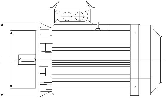
3.10 Dimensions International standards
IM mounting arrangements
This is a sample of a typical dimension drawing. Dimension drawings areavailable in catalogs, and on the ABB web site.
L
HD
H
E C B
K
|
B’ |
A |
M
D S F
45°GA
29

M S
P N
45°
Letter symbols for the most common dimensions:
|
A = distance between center lines of fixing holes (end view) |
F = width of the keyway of the shaft extension at D-end |
L = overall length of the motor with a single shaft extension |
||||
|
B = distance between the center lines of the fixing holes (side view) B’ = distance between the center lines of the auxiliary fixing holes C = distance of the shoulder on the shaft at D-end to the center line of the mounting holes in the nearest feet D = diameter of the shaft extension at D-end |
GA = distance from the top of the key to the opposite surface of the shaft extension at D-end H = distance from the centre line of the shaft to the bottom of the feet HD= distance from the top of the lifting eye, the terminal box, or other most salient part mounted on the top of the motor to the bottom of the feet |
M = pitch circle diameter of the fixing holes N = diameter of the spigot P = outside diameter of the flange, or in the case of a non-circular outline twice the maximum radial dimension S = diameter of the fixing holes in the mounting flange, or nominal diameter of thread. |
||||
|
E = length of the shaft extension from the shoulder at the D-end |
K = diameter of the holes or width of the slots in the feet of the motor |
|||||
30 LOW VOLTAGE MOTORS MOTOR GUIDE JULY 2019

![]()
|
— Table 3.1 Power – frame size correlation according to CENELEC |
— 3.11 Output power and frame size ratio Several countries have implemented a minimum energy efficiency performance standard (MEPS) through national legislation. IEC sets guidelines for testing and classification of motors according to standards. The following tables present two applications of power vs. frame size standards, one for Europe and another for Brazil. |
In Europe, the CENELEC standard EN 50347 lays down data for ratedoutput and mounting, i.e. shaft height, fixing dimensions and shaftextension dimensions, for various degrees of protection and sizes. Itcovers totally enclosed fan-cooled squirrel-cage motors at 50 Hz, framesizes 56 M to 315 M.
Standard output
|
Frame size |
Shaft extension diameter |
Rated output Flange number |
|||||||||||||||||||||||||||||||||
|
2 poles mm |
4,6,8 poles mm |
2 poles kW |
4 poles kW |
6 poles kW |
8 poles kW |
Free holes (FF) |
Tapped holes (FT) |
||||||||||||||||||||||||||||
|
56 9 9 0.09 or 0.12 |
0.06 or 0.09 |
F100 F65 |
|||||||||||||||||||||||||||||||||
|
63 11 11 0.18 or 0.25 |
0.12 or 0.18 |
F115 F75 |
|||||||||||||||||||||||||||||||||
|
71 14 14 0.37 or 0.55 |
0.25 or 0.37 |
F130 F85 |
|||||||||||||||||||||||||||||||||
|
80 19 19 0.75 or 1.1 |
0.55 or 0.75 |
0.37 or 0.55 |
F165 F100 |
||||||||||||||||||||||||||||||||
90S 24 24 1.5 1.1 0.75 0.37 F165 F115
90L 24 24 2.2 1.5 1.1 0.55 F165 F115
|
100L 28 28 3 2.2 or 3 1.5 0.75 or 1.1 |
F215 F130 |
112M 28 28 4 4 2.2 1.5 F215 F130132S 38 38 5.5 or 7.5 5.5 3 2.2 F265 F165132M 38 38 – 7.5 4 or 5.5 3 F265 F165160M 42 42 11 or 15 11 7.5 4 or 5.5 F300 F215 160L 42 42 18.5 15 11 7.5 F300 F215 180M 48 48 22 18.5 – – F300 180L 48 48 – 22 15 11 F300
200L 55 55 30 or 37 30 18.5 or 15 F350 22
225S 55 60 – 37 – 18.5 F400225M 55 60 45 45 30 22 F400250M 60 65 55 55 37 30 F500280S 65 75 75 75 45 37 F500280M 65 75 90 90 55 45 F500315S 65 80 110 110 75 55 F600315M 65 80 132 132 90 75 F600
—
Table 3.1
31
![]()
![]()
![]()
![]()
![]()
![]()
![]()
![]()
![]()
![]()
![]()
![]()
![]()
![]()
![]()
![]()
![]()
![]()
![]()
![]()
![]()
![]()
![]()
![]()
![]()
![]()
![]()
![]()
![]()
![]()
![]()
![]()
![]()
![]()
![]()
|
— Table 3.2 Power – frame size correlation according to NBR |
Brazil requires that motors imported to Brazil comply with national ABNT NBR 17094-1:2013 standards for low voltage motors. NBR 17094-1:2008 defines the frame-power relation as shown in the table below. Power kW Frame HP 2 poles 4 poles 6 poles 8 poles 0.18 0.25 63 63 71 71 0.25 0.33 63 63 71 80 0.37 0.50 63 71 80 90S 0.55 0.75 71 71 80 90L 0.75 1 71 80 90S 90L 1.1 1.5 80 80 90S 100L 1.5 2 80 90S 100L 112M 2.2 3 90S 90L 100L 132S 3.0 4 90L 100L 112M 132M 3.7 5 100L 100L 132S 132M 4.7 6 112M 112M 132S 160M 5.5 7.5 112M 112M 132M 160M 7.5 10 132S 132S 132M 160L 9.2 12.5 132S 132M 160M 180M/L 11.0 15 132M 132M 160M 180L 15.0 20 160M 160M 160L 180L 18.5 25 160M 160L 180L 200L 22 30 160L 180M 200L 225S 30 40 200M 200M 200L 225M 37 50 200L 200L 225M 250S 45 60 225S 225S 250S 250M 55 75 225M 225M 250M 280S 75 100 350M 250M 280S 280M 90 125 280S 280S 280M 315M 110 150 280M 280M 315M 315M 132 175 315S 315S 315M 355 150 200 315S 315S 315M 355 185 250 315S 315M 355 355 220 300 355 355 355 355 260 350 355 355 355 355 300 400 – 355 355 – 330 450 – 355 355 – 370 500 – 355 – – |
—
Table 3.2
32 LOW VOLTAGE MOTORS MOTOR GUIDE JULY 2019

—
Electrical design – induction motors
The electrical and mechanical design chapters of thisguide focus on induction motors.
Designing motors that deliver good all-round performanceinvolves a delicate balance between a number of factorswhich include efficiency, cost, temperature rise, vibration,noise, bearing selection, and slot and fan design. Only thecorrect balance will result in high quality motors which areefficient and reliable and provide a long service life.
33
—
Electrical design – induction motors
—
4.1 The induction motor
ABB’s low voltage induction motors are three-phase electric motorswhose rotating power is based on electromagnetic induction. Thecurrent led to motor windings creates a rotating magnetic field, whichinduces a voltage in the rotor bars. The bars form a closed circuit wherecurrent begins to circulate, forming another magnetic field. Themagnetic fields of the rotor and stator interact in such a way that therotor starts following the magnetic field of the stator, thus producingtorque.
In the nature of asynchronous motors, the rotor tends to fall behind thespeed of the magnetic field in the stator. When mechanical loadincreases on the motor shaft, the difference in speed (slip) increases, anda higher torque is produced.
ABB’s low voltage induction motors cover the power range from 0.06 to1000 kW.
34 LOW VOLTAGE MOTORS MOTOR GUIDE JULY 2019

![]()
|
— Figure 4.1 Safety margins per insulation class |
— 4.2 Insulation |
ABB uses class F insulation, which, with temperature rise class B, is themost commonly required insulation system for industrial motors.
Thermal class 130 (B)
• Nominal ambient temperature 40°C• Max. permissible temperature rise 80 K• Hot spot temperature margin 10 K
Thermal class 155 (B)
• Nominal ambient temperature 40°C• Max. permissible temperature rise 105 K• Hot spot temperature margin 10 K
Thermal class 180 (H)
• Nominal ambient temperature 40°C• Max. permissible temperature rise 125 K• Hot spot temperature margin +15 K
The use of class F insulation with class B temperature rise gives ABBproducts a 25 °C safety margin. This can be exploited to increase theloading of the motor for limited periods, to operate at higher ambienttemperatures or altitudes or with greater voltage and frequencytolerances. It can also be exploited to extend insulation life. For instance,already a 10 K temperature reduction has a relevant effect on insulationlifetime.
C
|
180 |
15 |
||||||||||||
|
155 130 120 |
Hotspot temperature margin |
10 |
10 |
||||||||||
|
Permissible temperature rise |
80 105 125 |
||||||||||||
40
|
Maximum ambient temperature |
40 40 40 |
||||||
|
Insulation class Maximum winding temperature |
B F H 130 155 180 |
||||||
—
Figure 4.1
35
![]()
![]()
![]()
![]()
![]()
![]()
|
— Table 4.1 Permitted output in high ambient temperatures or at high altitudes |
— 4.3 Thermistors Thermistors are temperature-dependent resistors inserted inside the winding heads − one for each phase − to control motor temperature. Under a certain temperature, the thermistor shows a fairly constant low resistance, but from a certain temperature upwards this resistance dramatically increases and the relay connected to thermistors will act. The resistance change is transformed into connection signals (warning or disconnection) resulting in thermal machine protection. |
—
4.4 Ambient temperatures and high altitudes
Normal motors are designed for operation at a maximum ambienttemperature of 40 °C and at a maximum altitude of 1000 meters abovesea level. If a motor is operated at higher ambient temperatures, it shouldbe derated according to the table below. Note that when the output power of a standard motor is derated, the relative values, such as IS/IN, incatalogs will change.
Ambient Temperature, °C 30 40 45 50 55 60 70 80
Permitted output, % of rated output 107 100 96.5 93 90 86.5 79 70
Height above sea level, m 1000 1500 2000 2500 3000 3500 4000
Permitted output, % of rated output 100 96 92 88 84 80 76
—
Table 4.1
36 LOW VOLTAGE MOTORS MOTOR GUIDE JULY 2019
—
4.5 Starting methods
The most common motor starting methods are introduced next. Theyare: direct-on-line and star-delta starting, and starting with a softstarteror variable speed drive.
Connection transients
It is important to remember that the term ‘starting current’ refers to asteady-state root-mean-square (rms) value. This is the value measuredwhen, after a few cycles, the transient phenomena have died out. Thepeak value of the transient current may be about 2.5 times the steady-state starting current, but decays rapidly. The starting torque of themotor behaves similarly, and this should be borne in mind if the momentof inertia of the driven machine is high, since the stresses on the shaftand coupling can be great.
4.5.1 Direct-on-line (DOL) starting
The simplest way to start a squirrel cage motor is to connect it directly tothe mains supply. In this case, a switch gear e.g. a contactor is the onlystarting equipment required. However, the limitation of this method is thatit results in a high starting current, often several times the rated current ofthe motor. Also the starting torque is very high, and may result in highstresses on the couplings and the driven application. Even so, it is thepreferred method except when there are special reasons for avoiding it.
4.5.2 Star-delta starting
If it is necessary to restrict the starting current of a motor because ofsupply limitations, the star-delta (Y/Δ) method can be employed. When amotor wound for 400 V/Δ, for instance, is started with winding Yconnected, this method will reduce the starting current to about 30 percent of the current reached with DOL, and the starting torque will bereduced to about 25 per cent of its DOL value.
However, before using this method, it must be determined whether thereduced motor torque is sufficient to accelerate the load over themotor’s speed range.
Contact your nearest ABB sales office for the MotSize dimensioning tool,or download it from our web site. ABB offers a full range of low voltageproducts for motor starting and control.
37


|
A sample taken from a dimensioning program showing DOL starting curves for a cast iron motor: 1. Starting torque at U n 2. Starting torque at 80 % U n 3. Torque load |
A sample taken from a dimensioning program showing Y/Δ starting curves for an aluminum motor: 1. Starting torque at U n 2. Starting torque at 80 % U n 3. Torque load |
|||||
|
— Figure 4.2 |
— Figure 4.3 |
|||||
|
— Figure 4.2 DOL starting — Figure 4.3 Star- delta starting |
4.5.3 Softstarters A softstarter limits the starting current of the motor and so provides a smooth start. The magnitude of the starting current is directly dependent on the static torque requirement during a start and on the mass of the load to be accelerated. ABB softstarters have adjustable settings to meet any application requirements. Gradually increasing the motor voltage, and thereby torque, results in a very smooth start. When the motor is well up in speed, it is common to bypass the softstarter to avoid power loss from the semiconductors during continuous operation. To bypass the softstarter it is common to use an externally mounted, AC-1 rated contactor. |
|||||
A bypass contact can also be built into the softstarter like in ABB’ssoftstarter ranges PSR, PSE, and PSTB. These softstarters are among themost compact available in the market.
In the ABB softstarter, the main circuit is controlled by semiconductorsinstead of mechanical contacts. Each phase is provided with two anti-parallel connected thyristors, which allows current to be switched at anypoint within both positive and negative half-cycles.
Lead time is controlled by the firing angle of the thyristor which, in turn,is controlled by a built-in printed circuit board.
38 LOW VOLTAGE MOTORS MOTOR GUIDE JULY 2019


|
— Figure 4.4 Impact of softstarters on current and torque |
Current Torque DoL DoL Y/ |
Y/ |
|||||||
|
— Figure 4.5 ABB softstarters |
Softstart |
Softstar |
|||||||
—
Figure 4.4
—
Figure 4.5
4.5.4 Starting with a variable speed drive
Speed regulation by a variable speed drive is a great advantage whenthere is need to adjust speed during continuous run, but it is usually notthe optimal solution only for starting and stopping the motor.
With a frequency converter, the rated motor torque is available already ata low speed, and the starting current is low, between 0.5 and 1 timesrated motor current, and at maximum 1.5 times nominal current. Anotheravailable feature in drives is softstop, which is useful when a smoothstop is equally desirable as a smooth start, for example in operatingwater pumps or running conveyor belts.
39

![]()
![]()
![]()
|
— Table 4.2 Maximum starting times in seconds for occasional starting, single- speed motors |
— 4.6 Starting limitations Starting time Starting time is a function of load torque, inertia and motor torque. As the starting current is always much higher than the rated current, an excessively long starting period will cause harmful temperature rise in the motor. The high current also causes electromechanical stress on the motor. |
Permitted starting time
In view of temperature rise, the starting time must not exceed the timespecified in the table. The figures in the table apply to starting from normaloperating temperature. When starting from cold, the figures can be doubled.
Number of poles Motor size Starting method 2 4 6 856 DOL 25 40 NA NA63 DOL 25 40 NA NA71 DOL 20 20 40 4080 DOL 15 20 40 4090 DOL 10 20 35 40100 DOL 10 15 30 40112 DOL 20 15 25 50 Y/D 60 45 75 150
132 DOL 15 10 10 60 Y/D 45 30 30 20
160 DOL 15 15 20 20 Y/D 45 45 60 60
180 DOL 15 15 20 20 Y/D 45 45 60 60
200 DOL 15 15 20 20 Y/D 45 45 60 60
225 DOL 15 15 20 20 Y/D 45 45 60 60
250 DOL 15 15 20 20 Y/D 45 45 60 60
280 DOL 15 18 17 15 Y/D 45 54 51 45
315 DOL 15 18 16 12 Y/D 45 54 48 36
355 DOL 15 20 18 30 Y/D 45 60 54 90
400 DOL 15 20 18 30 Y/D 45 60 54 90
450 DOL 15 20 18 30 Y/D 45 60 54 90
—
Table 4.2
40 LOW VOLTAGE MOTORS MOTOR GUIDE JULY 2019

![]()
![]()
![]()
![]()
![]()
![]()
![]()
![]()
Permitted frequency of starting and reversing
When a motor is subjected to frequent starting, it cannot be loaded at itsrated output because of thermal starting losses in the windings.Calculating the permissible output power can be based on the number ofstarts per hour, the moment of inertia of the load, and the speed of theload. Mechanical stresses may also impose a limit below that of thermalfactors.
|
Permitted output power P = |
m P 1− N m o |
P
N = rated output of motor in continuous duty
(JM + J’L)
m = x X
J
m
X = number of starts per hour
JM = moment of inertia of motor in kgm2
J’L = moment of inertia of load in kgm2, recalculated for the motor shaft, i.e. multiplied by (load speed /motor speed)2. The moment
of inertia J (kgm2) equals ¼ GD2 in kpm2.
m
o = highest permitted number of starts per hour for motor at no load,
as stated in the table at right.
Highest permitted number of reversals per hour at no load mr = m0 /4.
41

![]()
![]()
![]()
|
— Table 4.3 Highest permitted number of starts/hour at no load, m 0 |
Number of poles Motor size 2 4 6 8 56 12000 9000 – – 63 A, B 11200 8700 – – 71 A, B 9100 8400 16800 15700 80 A, B 5900 8000 16800 11500 90 L 3500 7000 12200 11500 100 L 2800 – 8400 – |
112 M 1700 6000 9900 16000
132 M 1700 2900 4500 6600
160 ML 650 – – 5000
180 ML 400 1100 – –
200 ML 385 – 1900 –
225 SM – 900 – 2350
250 SM 300 900 1250 2350
280 SM, ML 125 375 500 750
315 SM, ML 75 250 375 500
355 SM, ML, LK 50 175 250 350
400 L, LK 50 175 250 350
450 L On request
—
Table 4.3
42 LOW VOLTAGE MOTORS MOTOR GUIDE JULY 2019
![]()
![]()
![]()

![]()
![]()
![]()
![]()
|
— Table 4.4 Speed constant K1 as a function of frequency and pole pairs. |
Starting characteristics Catalogs usually state the maximum starting time as a function of motor size and speed. However, the standard IEC 60034-12 specifies the permitted moment of inertia of the driven machine instead of starting time. For small motors, the thermal stress is greatest in the stator winding, whereas for larger motors it is greatest in the rotor winding. |
If the torque curves for the motor and the load are known, the startingtime can be calculated with the following equation.
|
TM – TL = (JM + JL) x |
dω dt |
where
TM = motor torque, Nm T
L = load torque, Nm
JM = moment of inertia of the motor, kgm2 JL = moment of inertia of the load, kgm2 ω = angular velocity of the motor
In case of gearing TL and JL will be replaced by T’L and J’L respectively.
If the starting torque TS and maximum torque Tmax of the motor, togetherwith the nature of the load, are known, the approximate starting time can be calculated with the following equation.
(JM + J’L)
tst = x K1
T
acc
where
tst = starting time, s
Tacc = acceleration torque, Nm
f ) where p represents the number of
K1 = speed constant (2ϕ p
pole pairs
|
Speed constant |
Poles 2 4 6 8 10 |
Frequency Hz |
nm 3000 1500 1000 750 600
K
1 314 157 104 78 62 50
n
m 3600 1800 1200 900 720
K
1 377 188 125 94 75 60
—
Table 4.4
43


![]()
![]()
![]()
![]()
![]()
The average value for TM:
TM = 0.45 x (Ts + Tmax)T
acc = TM – KL x TL
KL can be obtained from the table below:
Lift motion Fan Piston pump Flywheel
K
L 1 1/3 0.5 0
Examples from the ABB calculation program on starting time
If there is gearing between the motor and the driven machine, the loadtorque must be recalculated to motor speed with the following formula.
|
T’L = TL x |
n n L M |
The moment of inertia must also be recalculated:
|
J’L = JL x |
n L n M |
2 |
44 LOW VOLTAGE MOTORS MOTOR GUIDE JULY 2019
Examples of starting performance with various load torques 4-pole motor, 160 kW, 1475 r/min
Torque of the motor T
N = 1040 Nm
Ts = 1.7 x 1040 = 1768 NmT
max = 2.8 x 1040 = 2912 Nm Moment of inertia of motor: J
M = 2.5 kgm2 The load is geared down in a ratio of 1:2
Torque of the load
TL = 1600 Nm at nL = nM/2 r/min
T’L = 1600 x 1/2 = 800 Nm at nM r/min
Moment of inertia of the load
JL = 80 kgm2 at nL = nM/2 r/min
J’L = 80 x (½)2 = 20 kgm2 at nM r/min
Total moment of inertia J
M + J’L at nM r/min
2.5 + 20 = 22.5 kgm2
45


![]()


![]()
![]()
![]()
![]()
|
Example 1: TL = 1600 Nm T’ L = 800 Nm Constant during acceleration T T acc = 0.45 x (TS + Tmax) – T’L acc = 0.45 x (1768 + 2912) – 800 = 1306 Nm |
Torque Lift motion |
T’L |
Speed |
(J
M + J’L)
tst = x K1
T
acc
22.5 x 157
tst = = 2.7 s 1306
|
Example 2: T L = 1600 Nm T’L = 800 Nm Linear increase during acceleration T acc = 0.45 x (TS + Tmax) – ½ x T’L Tacc = 0.45 x (1768 + 2912) – ½ x 800 = 1706 Nm |
Piston pump |
Torque |
T’L |
||||||
|
tst = (JM + J’L) x K1/Tacc |
Speed |
||||||||
157
tst = 22.5 x = 2.1 s 1706
|
Example 3: T L = 1600 Nm T’L = 800 Nm Square-law increase during acceleration T T acc = 0.45 x (TS + Tmax) – ⅓ x T’L acc = 0.45 x (1768 + 2912) – ⅓ x 800 = 1839 Nm |
Fan |
Torque |
T’L |
||||||||||||||
|
(JM + J’L) tst = x K1 T acc 22.5 x 157 t st = = 1.9 s 1839 |
Speed |
||||||||||||||||
|
Example 4: TL = 0 T acc = 0.45 x (TS + Tmax) Tacc = 0.45 x (1768 + 2912) = 2106 Nm |
Flywheel |
Torque |
|||||||||||||||
|
(JM + J’L) tst = x K1 T acc 22.5 x 157 tst = = 1.7 s 2106 |
Speed |
||||||||||||||||
46 LOW VOLTAGE MOTORS MOTOR GUIDE JULY 2019


![]()
—
4.7 Duty types
The duty types are indicated by S1…S10 according to IEC 60034-1 andVDE 0530 Part 1. The outputs given in the catalogs are based oncontinuous running duty, S1, with rated output. In the absence of anindication of the rated duty type, continuous running duty is assumedwhen considering motor operation.
|
S1 Continuous running duty Operation on constant load of sufficient duration for thermal equilibrium to be reached. Designation S1. |
P |
N
|
S2 Short-time duty Time shorter than that required to reach thermal equilibrium, followed by a rest and a de-energized period of sufficient duration to allow motor temperature to reach ambient termperature or cooling temperature. 10, 30, 60, and 90 minutes are recommended for the rated duration of the duty cycle. Designation for example S2 60 min. |
P |
N |
Time Time |
||||||||||||||
|
S3 Intermittent duty A sequence of identical duty cycles, each including a period of operation at constant load, a rest and a de-energized period. The duty cycle is too short for thermal equilibrium to be reached. The starting current does not significantly affect temperature rise. Recommended values for the cyclic duration factor are 15, 25, 40, and 60 percent. The duration of one duty cycle is 10 min. Designation for example S3 25 %. |
P |
N R One duty cycle |
Time |
||||||||||||||
|
Cyclic duration factor = |
N N + R |
x 100 % |
|||||||||||||||
Explanation of symbols used in this and the following figures
P = output power F = electrical braking PD = acceleration V = operation of no load
N = full load
N = operation under rated condition R = at rest and de-energized
47


![]()
![]()
![]()
S4 Intermittent duty with starting A sequence of identical
One duty cycle
duty cycles, each cycleincluding a significantperiod of starting,
P
operation at constant load,
D N R Time
a rest and a de-energized
period. The cycle-time is too short for thermal equilibrium to be reached.In this duty type, the motor is brought to rest by the load or by mechanical braking which does not thermally load the motor. Thefollowing parameters are required to fully define the duty type: the cyclicduration factor, the number of duty cycles per hour (c/h), the moment of inertia of the load (JL) and the moment of inertia of the motor (JM).
Designation for example S4 25 % 120 c/h J
L = 0.2 kgm2 JM = 0.1 kgm2.
|
Cyclic duration factor = |
D + N D + N + R |
x 100 % |
S5 Intermittent duty with starting and electrical braking A sequence of identical
One duty cycle
duty cycles, each cycle Pconsisting of a significantstarting period, a period of
operation at constant load,
Time
a period of rapid electric
F braking, a rest and a de-
D N R
energized period. The duty
cycles are too short for thermal equilibrium to be reached. The followingparameters are required to fully define the duty type: the cyclic durationfactor; the number of duty cycles per hour (c/h), the moment of inertia of the load (J
L) and the moment of inertia of the motor (JM).
Designation for example S5 40 % 120 c/h J
L = 2.6 kgm2 JM = 1.3 kgm2.
|
Cyclic duration factor = |
D + N + F D + N + F + R |
x 100 % |
S6 Continuous operation periodic duty
A sequence of identical duty cycles, each cycle consisting of a period atconstant load and a period of operation at no-load. The duty cycles aretoo short for thermal equilibrium to be reached. Recommended valuesfor the cyclic duration factor are 15, 25, 40, and 60 percent. The durationof the duty cycle is 10 min.
|
Designation for example S6 40 %. Cyclic duration factor = 100 % x |
N N + V |
48 LOW VOLTAGE MOTORS MOTOR GUIDE JULY 2019


![]()
![]()
![]()
S7 Continuous operation periodic duty with electrical braking A sequence of identical
P
duty cycles, each cycle
One duty cycle
consisting of a startingperiod, a period of operation at constant load,
Time
and a period of braking.
D N F
The braking method is
electrical braking such as counter-current braking. The duty cycles aretoo short for thermal equilibrium to be reached. The following parameters are required to fully define the duty type: the number of duty
cycles per hour (c/h), the moment of inertia of the load (Jmoment of inertia of the motor (J
L), and the M).
Designation for example S7 500 c/h J
L = 0.08 kgm2 JM = 0.08 kgm2.
S8 Continuous-operation periodic duty with related load speed changes A sequence of identical duty cycles, each cycle
One duty cycle
P
consisting of a startingperiod, a period of operation at constant load
Time corresponding to a
predetermined speed,
D N F1 N2 F2 N3
followed by one or more
periods of operation at other constant loads corresponding to differentspeeds. There is no rest or a de-energized period. The duty cycles are tooshort for thermal equilibrium to be reached. This duty type is used forexample by pole-changing motors. The following parameters are requiredto fully define the duty type: the number of duty cycles per hour (c/h), the moment of inertia of the load (JL), the moment of inertia of the motor (JM),and the load, speed, and cyclic duration factor for every operation speed.
Designation for example S8 30 c/h JL = 63.8 kgm2 JM = 2.2 kgm2.
24 kW 740 r/min 30%60 kW 1460 r/min 30%45 kW 980 r/min 40%
|
Cyclic duration factor 1 = Cyclic duration factor 2 = Cyclic duration factor 3 = |
D + N 1 D + N 1 + F1 + N2 + F2 + N3 F1 + N2 D + N1 + F1 + N2 + F2 + N3 F2 + N3 D + N 1 + F1 + N2 + F2 + N3 |
x 100 % x 100 % x 100 % |
49

S9 Duty with non-periodic load and speed variationsA duty in which, generally, load and speed vary non-periodically withinthe permissible operating range. This duty includes frequently appliedoverloads that may greatly exceed the full loads. For this duty type,suitable full load values should be taken as the basis of the overloadconcept.
S10 Duty with discrete constant loads and speeds A duty consisting of a specific number of discrete values of load (or equivalent loading) and if applicable, speed, each load/speed combination being maintained for sufficient time to allow the machine to reach thermal
equilibrium. The minimum load within a duty cycle may have the valuezero (no-load or de-energized and at rest).
The appropriate designation is S10, followed by the per-unit quantitiesplΔt for the respective load and its duration, and the per-unit quantity TLfor the relative thermal life expectancy of the insulation system. Thereference value for the thermal life expectancy is the thermal lifeexpectancy at rating for continuous running duty and permissible limitsof temperature rise based on duty type S1. For a time de-energized andat rest, the load shall be indicated by the letter r.
Example: S10 plΔt = 1.1/0.4; 1/0.3; 0.9/0.2; r/0.1 TL = 0.6
The value of TL should be rounded to the nearest multiple of 0.05.
For this duty type a constant load appropriately selected and based on duty type S1 shall be taken as the reference value (‘Pref’ in the figure) forthe discrete loads.
Note: The discrete values of load will usually be equivalent loading based on integration over aperiod of time. It is not necessary that each load cycle be exactly the same, only that each loadwithin a cycle be maintained for sufficient time for thermal equilibrium to be reached, and thateach load cycle is capable of being integrated to give the same relative thermal life expectantly.
50 LOW VOLTAGE MOTORS MOTOR GUIDE JULY 2019
![]()
![]()
![]()
![]()
![]()

![]()
![]()
![]()
![]()
![]()
|
— Table 4.5 Permitted output in short time duty S2 as percentage of rated output — Table 4.6 Permitted output in intermittent duty S3 as percentage of rated output |
— 4.8 Uprating Because of the lower temperature rise in the motor in short-time or intermittent duty, it is usually possible to take higher output from the motor in these types of duty than in continuous duty, S1. The tables below show some examples of this. Attention must be paid to the motor’s maximum torque, T max/TN must be >1.8 referred to increased output.
Short-time duty S2 Poles |
30 min 2 105 125 130
4 – 8 110 130 130
60 min 2 – 8 100 110 115
—
Table 4.5
|
Intermittent duty S3 Poles |
Permitted output as % of rated output in S1 continuous duty for motor size 56 – 100 112 – 250 280 – 450 |
15 % 2 115 145 140
4 140 145 140
6, 8 140 140 140
25 % 2 110 130 130
4 130 130 130
6, 8 135 125 130
40 % 2 110 110 120
4 120 110 120
6, 8 125 108 120
60 % 2 105 107 110
4 110 107 110
6, 8 115 105 110
—
Table 4.6
51
—
4.9 Efficiency and types of losses
Efficiency of a motor is a measure of how well it is capable of convertingelectrical energy into mechanical work. Lost energy is emitted in the form ofheat. To increase efficiency, losses have to be reduced.
Motor losses can be divided into five main categories. The first category is ironlosses in the core, the second windage and friction losses. Load losses, whichvary with the load, are classified into copper losses in the stator, rotor losses,and stray load losses. All losses can be influenced by motor design andconstruction solutions.
Constant losses
Iron losses in the core are caused by the energy required to overcome theopposition to changing magnetic fields in the core material. These lossescan be reduced by using better-quality steel and by lengthening the core toreduce magnetic flux density.
Windage and friction losses are caused by air resistance and bearing friction.Improved bearing design and bearing seal selection, air flow and fan designaffect these losses. The fan must be large enough to provide adequate cooling,but not so large as to reduce efficiency and increase noise. To reach an optimalcooling effect in each ABB motor, blade sizes and pitches vary in different fanmodels.
Load losses
Of load losses, stator copper losses (also referred to as I2R losses) are causedby heating from the current flow through the resistance of the stator winding.Techniques for reducing these losses include optimizing the stator slot design.
Rotor losses are depending on the slip. These losses are reduced for example byincreasing the size of the conductive bars and end rings to produce lowerresistance. Stray load losses are the result of leakage fluxes induced by loadcurrents. These can be decreased by improving slot geometry.
Completely new motor designs are also developed to increase efficiencybeyond known limits. The synchronous reluctance motor is an example of thesenew designs.
Efficiency values for rated output are listed in the technical data tables in ABBproduct catalogs.
52 LOW VOLTAGE MOTORS MOTOR GUIDE JULY 2019

—
4.10 Power factor
A motor consumes both active power, which it converts into mechanicalwork, and reactive power, which is needed for magnetization and whichis not converted to work.
The active and reactive power, represented in the diagram (below) by Pand Q, together give the apparent power S. The ratio between activepower, measured in kW, and apparent power, measured in kVA, is knownas the power factor. The angle between P and S is usually designated asϕ, and the power factor itself is designated as cos ϕ.
Power factor is usually between 0.7 and 0.9. It is lower for small motorsand higher for large motors.
Power factor is determined bymeasuring the input power,voltage and current at ratedoutput power. The powerfactor stated is subject to atolerance of (1-cos ϕ)/6 .
If there are many motors in an installation, a lot of reactive power will beconsumed and therefore the power factor will be lower. For this reason,power suppliers sometimes require the power factor of an installation tobe increased. This is done by connecting capacitors to the supply whichabsorb reactive power and thus raise the power factor.
Reactive-power compensation
With phase compensation, the capacitors are usually connected in parallelwith the motor, or with a group of motors. However, in some cases, over-compensation can cause an induction motor to self-excite and run as agenerator. Therefore, to avoid complications, it is a normal practice not tocompensate for more than the no-load current of the motor.
The capacitors must not be connected in parallel with single phases ofthe winding; such an arrangement may make the motor difficult orimpossible to start with star-delta starting.
If a two-speed motor with separate windings has phase compensationon both windings, the capacitors should not remain in circuit on theunused winding.
53
![]()
![]()
![]()
![]()
![]()
![]()
![]()
![]()
![]()
![]()
![]()
![]()
![]()
![]()
![]()
![]()
![]()
![]()
![]()
![]()
![]()
![]()
![]()
![]()
![]()
![]()
![]()
![]()
![]()
![]()
![]()
![]()
![]()
![]()
![]()
![]()
![]()
![]()
![]()
![]()
![]()
![]()
![]()
![]()
![]()
![]()
|
— Table 4.7 Phase compensation |
Under certain circumstances, such capacitors can cause increased heating of the winding and possibly also vibration. |
Constant K cos ϕ Compensation to cos ϕ = without compensation 0.95 0.90 0.85 0.80 0.50 1.403 1.248 1.112 0.982 0.51 1.358 1.202 1.067 0.936 |
||||
|
The following formula is used to calculate the size (per phase) of a capacitor for a mains frequency of 50 Hz: |
0.52 1.314 1.158 1.023 0.892 0.53 1.271 1.116 0.980 0.850 0.54 1.230 1.074 0.939 0.808 0.55 1.190 1.034 0.898 0.768 0.56 1.150 0.995 0.859 0.729 |
|||||
|
C = 3.2 · 106 · |
Q U 2 |
0.57 1.113 0.957 0.822 0.691 0.58 1.076 0.920 0.785 0.654 0.59 1.040 0.884 0.748 0.618 |
||||
|
Where C = capacitance, μF U = capacitor voltage, V Q = reactive power, kvar. |
0.60 1.005 0.849 0.713 0.583 0.61 0.970 0.815 0.679 0.548 0.62 0.937 0.781 0.646 0.515 0.63 0.904 0.748 0.613 0.482 0.64 0.872 0.716 0.581 0.450 0.65 0.841 0.685 0.549 0.419 |
|||||
|
Reactive power is obtained from: |
0.66 0.810 0.654 0.518 0.388 0.67 0.779 0.624 0.488 0.358 |
|||||
|
P Q = K · P η Where K = constant from table on right P = rated power of motor, kW η = efficiency of motor |
0.68 0.750 0.594 0.458 0.328 0.69 0.720 0.565 0.429 0.298 0.70 0.692 0.536 0.400 0.270 0.71 0.663 0.507 0.372 0.241 0.72 0.635 0.480 0.344 0.214 0.73 0.608 0.452 0.316 0.186 0.74 0.580 0.425 0.289 0.158 0.75 0.553 0.398 0.262 0.132 0.76 0.527 0.371 0.235 0.105 0.77 0.500 0.344 0.209 0.078 0.78 0.474 0.318 0.182 0.052 0.79 0.447 0.292 0.156 0.026 0.80 0.421 0.266 0.130 0.81 0.395 0.240 0.104 0.82 0.369 0.214 0.078 0.83 0.343 0.188 0.052 0.84 0.317 0.162 0.026 0.85 0.291 0.135 0.86 0.265 0.109 0.87 0.238 0.082 0.88 0.211 0.055 0.89 0.184 0.027 0.90 0.156 |
|||||
—
Table 4.7
54 LOW VOLTAGE MOTORS MOTOR GUIDE JULY 2019
![]()
![]()
![]()
![]()
![]()
![]()
![]()
![]()
![]()
![]()
![]()
![]()
![]()
![]()
![]()
![]()
![]()
![]()
![]()
![]()
![]()
![]()
![]()
![]()
![]()
![]()
![]()
|
— Table 4.8 Power factors for induction motors |
Power factor values The power factors for rated output are listed in the technical data tables in product catalogs. |
The table below illustrates typical power factors. ABB suppliesguaranteed values on request.
As the table shows, a motor with a power factor of 0.85 has 3/4 loadvalue of 0.81, 1/2 load value of 0.72 and 1/4 value of 0.54.
Power factor cos ϕ
2 – 12 poles
1.25 x PN 1.00 x PN 0.75 x PN 0.50 x PN 0.25 x PN
0.92 0.92 0.90 0.84 0.68 0.91 0.91 0.89 0.83 0.66 0.90 0.90 0.88 0.82 0.64 0.89 0.89 0.87 0.81 0.62 0.88 0.88 0.86 0.80 0.60 0.88 0.87 0.84 0.76 0.58 0.87 0.86 0.82 0.73 0.56 0.86 0.85 0.81 0.72 0.54 0.85 0.84 0.80 0.71 0.52
0.84 0.83 0.78 0.70 0.50
0.84 0.82 0.76 0.66 0.46 0.84 0.81 0.74 0.63 0.43 0.83 0.80 0.73 0.60 0.40 0.82 0.79 0.72 0.59 0.38 0.82 0.78 0.71 0.58 0.36 0.81 0.77 0.69 0.55 0.36 0.81 0.76 0.68 0.54 0.34 0.80 0.75 0.67 0.53 0.34 0.79 0.74 0.66 0.52 0.32 0.78 0.73 0.65 0.51 0.32 0.78 0.72 0.62 0.48 0.30 0.78 0.71 0.61 0.47 0.30 0.77 0.70 0.60 0.46 0.30
—
Table 4.8
55
![]()
![]()
![]()
![]()
![]()
![]()
![]()
![]()
![]()
![]()
![]()
![]()
![]()
![]()
![]()
![]()
![]()
![]()
![]()
![]()
![]()
![]()
![]()
![]()
![]()
![]()
![]()
![]()
|
— Table 4.9 Air flow and air speed |
— 4.11 Air flow and air speed |
When the motor is ordered without self-cooling, attention must be paidto ensure sufficient cooling by other means. Air flow and air speedbetween the ribs of the motor frame must at the minimum meet thevalues given in the table below. The values correspond to 50 Hz networksupply; with 60 Hz supply an increase of 20 % is needed.
|
Shaft height |
Pole number |
Air speed m/s |
Air flow m3/s |
Shaft height |
Pole number |
Air speed m/s |
Air flow m3/s |
280 2 9.6 0.46 355 2 10 0.82
4 8.5 0.39 4 13 1.1
6 6.5 0.32 6 11.5 1.0
8 7.6 0.36 8 8.5 0.7
315 SM. ML 2 8.3 0.46 400 2 15 1.4
4 9.4 0.56 4 13 1.25
6 7.5 0.4 6 11 1.1
8 7.6 0.43 8 8 0.8
315 LK 2 7.8 0.47 450 2 15 2.0
4 15 0.80 4 15 2.0
6 9.5 0.53 6 13 1.7
8 8.8 0.49 8 10 1.25
—
Table 4.9
56 LOW VOLTAGE MOTORS MOTOR GUIDE JULY 2019


![]()
|
— Figure 4.6 Connection of three-phase single-speed motors |
— 4.12 Connection diagrams Connection of three phases, single speed motors |
—
Figure 4.7 Connection options for two-speed motors
Δ-connection
Y-connection
—
Figure 4.6
Connection of two-speed motors
Two-speed motors are normally connected as illustrated below; directionof rotation is discussed in the Standards chapter. Motors of normaldesign have six terminals and one earth terminal in the terminal box.Motors with two separate windings are normally Δ-Δ connected. Theycan also be Y/Y, Y/Δ or Δ/Y connected. Motors with one winding,Dahlander-connection, are connected Δ/YY when designed for constanttorque drives. For a fan drive, the connection is Y/Y Y.
A connection diagram is supplied with every motor.
When starting a motor using Y Δ connection, always refer to the connection diagram supplied by the starter manufacturer.
1. Two separate windings Y/Y
2. Two separate windings ∆/∆
3. Dahlander-connection ∆/YY
4. Dahlander-connection Y/YY
—
Figure 4.7
57

58 LOW VOLTAGE MOTORS MOTOR GUIDE JULY 2019

—
Mechanical design
This chapter introduces the main parts of an inductionmotor and the mechanical design of the parts that are ofhighest interest from motor usage point of view: theframe and terminal box, bearings, and drain holes.
The basics of radial and axial forces as well as the standardsthat define requirements for motor balancing, vibrationmeasurement, and surface treatment are also discussed.
59
—
Mechanical design
—
5.1 Motor construction
The induction motor is an electric motor that uses electric power toinduce rotation of the rotor. The main parts of the induction motor andtheir functions are as follows.
Stator – the stationary part of the motor which surrounds the rotor. Thestator consists of copper wires (windings) wound in between the stator’sslots to carry supply current and to induce a rotating magnetic field tointeract with the rotor.
Rotor – the rotating core part of the motor fixed to the shaft. The rotorconsists of a stack of thin steel laminations and a squirrel-cageconstruction of conductive bars that react with the magnetic field of themotor and produce torque to turn the shaft.
Shaft – the rotating innermost part of the motor which transmits the rotor’s rotational power to the application fixed to the motor’s D-end.
Bearing – bearings surround the motor’s shaft at both ends and reduce friction between the motor frame and shaft.
Frame – cast-iron or aluminum casing which covers the motor’s core parts and provides electrical connections.
D-end – the drive end of the motor.
N-end – the non-drive end of the motor.
60 LOW VOLTAGE MOTORS MOTOR GUIDE JULY 2019

|
— Figure 5.1 Cross-section of a cast-iron induction motor |
The following is a cross-section of a three-phase induction motor and its main parts. Terminals Raiting plate Winding Bearing for N Stator Rotor |
Bearing for D Frame
Fan
Shaft
Fan cover
Shaft key
—
Figure 5.1
—
5.2 Frame constructions
Totally enclosed electric motors are available in a choice of aluminum andcast iron frames for different application areas. Cast-iron-framed motorsare typically used in heavy industries where better durability againstchemicals and corrosion is required, whereas aluminum-framed motorsare better suited for lighter applications such as pumps and fans.
61


|
— Figure 5.2 Connection flange with cable |
— 5.3 Terminal boxes |
||
|
— Figure 5.3 Angle adapter and cable-sealing glands box |
The terminal box is mounted either on top of the motor or on either side of the motor. Technical details may vary from type to type, and the most recent information can be found in the relevant product catalogs. The terminal boxes of aluminum motors in sizes 56 to 180 are normally provided with knock-out openings, and sizes 200 to 250 have terminal boxes with two gland plates. |
||
The terminal boxes of cast-iron motors in sizes 71 to 250 are equippedwith blank cover plates for connection flanges. In motor sizes 280 to 450,the terminal box is equipped with cable glands or cable boxes (Figures
5.2 and 5.3). There is a wide range of cable glands and cable boxesavailable as options, also equipped with EMC modules and cable clamps.
The terminal box material is either cast iron or aluminum, depending onthe motor type. The main terminal box is attached either on top, on side, orat a 45 degree angle on the side. It may also be connected to the motorwith extended cables, so-called flying leads. In case of accessories such asthermistors or heating elements, one or more auxiliary terminal boxes maybe attached to the motor. Non-standard designs of terminal boxes, such asnon-standard size and degree of protection, are available as options.
A standard motor usually has six phase connections and at least oneearthing connection (Figures 5.4 and 5.5). The necessary connectionparts and a connection diagram are delivered together with the motor,under the terminal box cover.
|
— Figure 5.2 |
— Figure 5.3 |
62 LOW VOLTAGE MOTORS MOTOR GUIDE JULY 2019


—
Figures 5.4–5.5
|
— Figures 5.4–5.5 Typical terminal boxes in motor sizes 71 to 250 (5.4) and 280 to 315 (5.5) — Figure 5.6 Terminal box integrated in motor frame |
The terminal box in aluminum motors allows cable entry from both sides. In small motors, the box is integrated in motor frame and has a blind flange on with knock-out openings on both sides (Figure 5.6). Larger aluminum motors are equipped with two connection flanges on both sides. In cast iron motor sizes 71 – 132, the box is integrated in the frame, with connection on the right-hand side (viewed from the D-end). Sizes 160 – 355 have a terminal box that can be rotated 4×90°, and sizes 400 – 450 have a terminal box that can be rotated 2×180° to allow cable entry from either side of the motor. The 4×90° turnable box is available as an option for several other motor types as well. |
The degree of protection of a standard terminal box is IP 55.
—
Figure 5.6
To ensure that suitable connections are supplied for the terminal box, seethe specific product catalog for information on flange openings, cablediameters, and so forth.
63
—
5.4 Bearings
Motors are normally fitted with single row deep groove ball bearings. Thecomplete bearing designation is stated on the rating plate of most motortypes.
If the bearing in the D-end of the motor is replaced with roller bearingsNU- or NJ-, higher radial forces can be handled. Roller bearings areespecially suitable for belt-driven applications.
With high axial forces, angular contact ball bearings should be used. Thistype of bearing is usually needed when motors are mounted vertically.When ordering a motor with angular contact ball bearings, the method ofmounting and direction and magnitude of axial force must be specified.
Single angular contact bearings are not suitable for horizontally mountedmotors where low axial forces are possible. Double angular contact ballbearings arranged back to back or face to face are recommended in casethere are low axial forces in a horizontally mounted motor, or if thedirection of the axial force can change. See the product catalog of themotor in question for more specific information about bearings.
Bearing life
The normal bearing life L10h of a bearing is defined, according to ISO281, as the number of operating hours achieved or exceeded by 90 % ofidentical bearings in a large test series under specific conditions. 50 % ofbearings achieve at least five times this lifetime.
The nominal bearing life is the lifetime that 90 % of identical bearingsachieve or exceed before first signs of material weariness appear.A sufficient grease layer inside the bearing and usage in a correctapplication are preconditions for a nominal bearing life. By definition,10 % of bearings can fail before they reach the nominal bearing life.Consequently, bearing life should never be confused with warrantyperiod.
The usual values for bearing lifetime of standard motors are 40,000 h forbelt drive and 100,000 h for direct coupling.
64 LOW VOLTAGE MOTORS MOTOR GUIDE JULY 2019

|
— Figure 5.7 Bearing arrangements in Process performance cast iron motors, sizes 280 to 450 |
Bearing size Reliability is the main criteria for bearing size design, taking into account the most common types of application, load of the motor and motor size. ABB uses series 63 bearings which are of robust design for longer life and higher loadability. 62 series bearings have lower noise levels, higher maximum speeds, and lower losses. See product catalogs and motor rating plates for exact bearing types. |
—
Figure 5.7
—
5.5 Drain holes and humidity
Absolute humidity is the amount of water (g/m3) in a certain volume ofair. Its value, so-called saturation value, increases when temperatureincreases. Relative humidity is the ratio between absolute air humidityand saturation value at a certain ambient temperature. When air coolsbelow the temperature where the dew point is reached (relative humidityis 100 %), condensation on cold surfaces takes place.
Humidity is a risk not only to the external surface of the motor; it mayalso lead to internal corrosion.
When totally enclosed machines heat up, the air inside them expands;when they cool down the air volume decreases. The volume increase anddecrease depend on the temperature difference to the ambient air. Whenthe motor cools down, it may suck in particles and humidity that coulddamage bearings and insulation. The advantage of the drain holes is thatthey prevent ventilation through bearings and terminal box. Drain holescan be opened and closed with plastic plugs.
65
When temperature difference to ambient air is high, heating elementsfitted to the winding heads may be needed to prevent corrosion of thewindings. If humidity inside the motor is suspected, special measuressuch as insulation resistance measurement or drying in an oven need tobe taken to avoid permanent damage to the motor.
—
5.6 External radial and axial forces of the motor
Depending on the purpose of use, and in addition to the rotationaltorque which is always present when running the motor, the shaft endmay be affected by external radial or axial forces. Radial forces are thosethat are perpendicular to the shaft, while axial forces are linear with theshaft. The shaft end may also be exerted by both radial and axial forcesat the same time. The maximum radial and axial forces are given inproduct catalogs per each motor type in Newtons. In case of radialforces, it is essential to know the exact position of the load on the shaftextension. If the shaft extension will be affected simultaneously by bothradial and axial forces, the load capacity of the motor needs to bechecked case by case with ABB.
—
5.7 Balancing
The rotor is dynamically balanced in the keyway of the shaft extensionwith a half-sized key (half-key balancing) according to standard ISO 8821.Balancing with a full key or without a key are also available on request. Bydefault, ABB motors are balanced to grade G2.5 according to ISO 1940/1.Balancing to grade G1 is available on request. When the motor is orderedwith higher vibration class B (see Vibration), the rotor balancing grade isG1 by default.
There are two possibilities for checking balancing quality afterwards:removing the rotor out of the motor and placing it on a balancingmachine, or checking it by a vibration measurement tool. The latter canbe done as follows: Lift the motor with a lifting lug and leave it hanging,or place it standing on soft rubber, for example. Run the motor atnominal speed and check vibration level. The measured vibration levelshould be less than 1.5 mm/s (rms) for a new motor.
66 LOW VOLTAGE MOTORS MOTOR GUIDE JULY 2019

|
— Table 5.1 Limits of maximum vibration magnitude in displacement, velocity and acceleration (rms) for shaft height H |
— 5.8 Vibration Effective values (root mean squares, rms) of vibration velocity are defined in the IEC 60034-14 standard (see Table 5.1). Requirements apply across the measuring range of 10 to 1000 Hz. The purpose of this standard is to measure the vibration behavior of a machine alone at no load, under defined conditions in a reproducible and comparable way, the motor placed on elastic mounting. However, though vibration severity depends on the balancing grade used, it also essentially depends on the properties of coupling to the driven machine and coupling parts used. |
Possible origins of severe vibration of coupled motors can be incorrectbalancing (half key/full key), inaccurate alignment of the motor with acoupled machine, and resonance of the system (motor and foundation).ABB motors fulfill grade A vibration level by default.
Vibration is expressed in mm/s RMS.
|
Vibration grade |
Shaft height, mm mounting |
Displac. μm |
56 ≤ H ≤ 132 132 < H ≤ 280 H > 280
|
|||||||||||||||||||||||||||
|
A Rigid mounting |
25 1.6 2.5 35 2.2 3.5 45 2.8 4.4 |
|||||||||||||||||||||||||||||
|
Free suspension |
21 1.3 2.0 29 1.8 2.8 37 2.3 3.6 |
|||||||||||||||||||||||||||||
|
B Free suspension |
11 0.7 1.1 18 1.1 1.7 29 1.8 2.8 |
|||||||||||||||||||||||||||||
|
Rigid mounting |
– 14 0.9 1.4 24 1.5 2.4 |
|||||||||||||||||||||||||||||
—
Table 5.1
67

![]()
![]()
|
— Table 5.2 Atmospheric corrosivity categories and recommended environment |
— 5.9 Surface treatment The surface treatment categorization of ABB motors is based on the ISO 12944 standard. ISO 12994-5 divides paint system durability into three categories: low (L), medium (M), and high (H). Low durability corresponds to a lifetime of 2 – 5 years, medium to 5 – 15 years, and high durability to over 15 years. |
The durability range is not a guaranteed lifetime. Its purpose is to helpthe owner of the motor plan for appropriate maintenance intervals. Morefrequent maintenance may be required because of fading, chalking,contamination, wear and tear, or for other reasons.
ABB’s standard surface treatment is corrosivity category C3, durabilityrange M (which corresponds to medium corrosivity and mediumdurability). Special surface treatment is available in corrosivity categories.
C4 and C5-M, durability class M for both. See table below for moredetails. In addition, surface treatment according to the NORSOKstandard for offshore environments is available as an option.
The standard ABB paint color for motors is Munsell blue 8B 4.5/3.25.
Corrosivity category Outdoor atmospheres Indoor atmospheres Use in ABB motors
|
C1, very low Not used Heated buildings with clean atmospheres |
Not available |
||||||||||||||||||
|
C2, low Atmospheres with low level pollution, mostly rural areas. |
Unheated buildings where condensation may occur, such as depots and sports halls. |
Not available |
|||||||||||||||||
|
C3, medium Urban and industrial atmospheres, moderate sulfur dioxide pollution. Coastal areas with low salinity. |
Production rooms with high humidity and some air pollution; food processing plants, laundries, breweries, dairies. |
Standard treatment |
|||||||||||||||||
|
C4, high Industrial areas and coastal areas with moderate salinity. |
Chemical plants, swimming pools, coastal ship- and boatyards. |
Optional treatment, variant code 115 |
|||||||||||||||||
|
C5-I, very high (industrial) |
Industrial areas and coastal areas with high humidity and aggressive atmosphere. |
Buildings or areas with nearly permanent condensation and high pollution. |
Not available |
||||||||||||||||
|
C5 -M, very high (marine) |
Coastal and offshore areas with high salinity. |
Buildings or areas with nearly permanent condensation and high pollution. |
Optional treatment, variant code 754 |
||||||||||||||||
—
Table 5.2
68 LOW VOLTAGE MOTORS MOTOR GUIDE JULY 2019

— Noise
Noise is subject to strict regulations today, withmaximum permitted levels. Accordingly, ABB considersnoise reduction a major design criterion in thedevelopment of our motors.
69

— Noise
|
— Figure 6.1 Human hearing range |
6.1 Sound pressure level and sound power level Sound is pressure waves sent out by a source through the medium (usually air) in which it is immersed. Sound pressure is measured in decibels (dB) during a noise test. The ratio between the threshold of hearing and the threshold of pain is 1:10 000 000. As the pressure scale is so large and since we experience a 10 dB difference as a doubling of the perceived sound level, a logarithmic scale is employed where: |
Sound pressure level L
p= 10 log [(p/p0)2 ] [dB]
p
0 = 20 μPa is the threshold of hearing for an average person
p = measured pressure [Pa]
Sound pressure is measured in a test room to eliminate the effect ofreflected noise and external sources. A microphone is placed at variouspositions around the motor in order to measure sound radiation intodifferent directions. Usually the distance of the microphone from themotor surface is one meter. As the noise level varies in differentdirections due to the influence of internal sources, a tolerance of 3 dB isapplicable for the average sound pressure level. Information on soundpressure level is meaningful only if the distance from the sound source isstated. For example, Lp = 80 dB at a distance of one meter from a pointsound source corresponds to 70 dB at three meters.
|
The measured sound level Lp can be converted into power radiated from the sound source, to determine the sound power level Lw. The formula for this is: Lw = Lp + Ls (Ls is calculated from the area of the measurement surface, according to ISO). Thus, sound power level is usually a larger number than the corres- ponding sound pressure level. Care should be taken not to confuse the quantities. |
— Figure 6.1 |
70 LOW VOLTAGE MOTORS MOTOR GUIDE JULY 2019

![]()
![]()
![]()
|
— Figure 6.2 Filter characteristics for A-weighting |
The use of sound power instead of sound pressure to describe noise emission from a motor is encouraged: because sound pressure is a function of distance and environmental factors (reflections), sound power is fixed. There is an analogy to heating radiator: If you use a 1000 W electrical heater to warm up a room, the final temperature of the room depends on the insulation of the walls, room size etc. Here the temperature is analog to sound pressure. |
—
6.2 Weighting filters
Amplifiers and various filters are used when measuring compositesound. Normally only the LpA figure is given. It corresponds best withthe perception of the ear.
Filters let through an entire frequency range, but attenuate or amplifycertain parts of it. The resulting frequency curves resemble stylized 40-,70- and 100-phon curves for pure tones.
—
Figure 6.2
71

![]()
![]()
![]()
![]()
![]()
![]()
![]()
|
— Figure 6.3 Noise rating (NR) curves |
— 6.3 Octave bands |
Mean sound pressure level is measured with a broad band filter coveringthe entire frequency band. Measurement is also done with a narrow bandfilter to define noise level per octave band (frequency band), as theperception of the human ear is dependent on the octave band.
Octave band analysis
To get an idea of the character of composite sound, it has provenpractical to divide the frequency range into octave bands with a ratio of1:2 between the band limit frequencies. The frequency range is usuallyreferred to by the mid-frequency of the band. The measured dB figuresfor all octave bands are generally shown in the form of an octave banddiagram.
A system of noise rating curves known as NR curves has been developedunder ISO to express the subjective degree of disturbance from differentnoises. These curves are intended to be used when assessing the risk ofdamage to hearing. Similar systems are also available. NR curve numberssignify the degree of noise.
For the octave band with a mid-frequency of 1,000 Hz, the number isequal to the sound pressure level in dB. The NR curve that touches thenoise curve of the motor in question determines the motor’s noise rating.The table below illustrates the use of noise rating. It shows how long aperson can remain in a noisy environment without getting permanenthearing damage.
A ––– No risk of hearing
damage. The NR 85
curve touches the noise curve of the motor. The noise level is 88 dB(A).B —- Risk of hearing damage. The NR 88 curve touches the noise curve of the motor. The noise level is 90 dB(A).
NR Time per day85 > 5 hours90 = 5 hours95 = 2 hours105 < 20 minutes120 < 5 minutes
—
Figure 6.3
72 LOW VOLTAGE MOTORS MOTOR GUIDE JULY 2019

![]()
![]()
![]()
![]()
![]()
![]()
![]()
![]()
![]()
![]()
![]()
![]()
![]()
![]()
![]()
![]()
![]()
![]()
![]()
![]()
![]()
![]()
![]()
![]()
![]()
![]()
![]()

![]()
![]()
![]()
![]()
![]()
![]()
![]()
![]()
![]()
![]()
![]()
![]()
![]()
![]()
![]()
![]()
![]()
![]()
![]()
![]()
![]()
![]()
![]()
![]()
![]()
![]()
|
— Figure 6.4 Effect of sound sources on total sound pressure level |
— 6.4 Additional sound sources Perception of difference in sound level A difference of 1 dB in sound level is barely detectable, whereas a 10 dB difference is perceived as doubling or halving of the sound level. |
The diagrams below illustrate the total sound pressure level when severalsound sources are present. For example, diagram A shows that the soundpressure level will be 3 dB higher if the sound levels of two identicalsources are added together. Diagram B shows how the sound levelpressure changes when the sound sources have different pressure levels.
However, before logarithmic values can be added or subtracted, theymust be converted into absolute numbers. An easier way of adding orsubtracting sound sources is to use the diagrams below.
Increase in total sound pressure level Increase in total sound pressure level
Adding two different levels. When thedifference between the two soundpressure levels is greater than 10 dB, thelower level contributes so little to thetotal sound pressure level it may bedisregarded.
Adding several equal sound sources.Adding together two such sourcesincreases the total level by 3 dB; addingtogether four increases it by 6 dB,and so on.
—
Figure 6.4
73
![]()
![]()
![]()
—
6.5 Noise components of a motor
The total sound power emission from a motor can be considered acombination of three uncorrelated noise sources acting together. Thesesources are magnetic, cooling, and mechanical or rotational noisesources. Magnetic noise results from temporal and spatial variations ofmagnetic force distribution in the air gap. Operating a cooling fancreates most of the cooling noise. Rotational noise is generated when 1)an unsmooth body (rotor) rotates in a cavity that has obstacles anddiscontinuities, and 2) the shaft and the bearings interact. Themagnitude of each source depends on motor type. The major factorsaffecting each of the sources in a motor are:
Magnetic noise Pmagn [W] • shaft load
• voltage, current, frequency, and supply type• winding parameters
• slot geometry
• saturation, eccentricity, etc.
Cooling noise Pcool [W]
• fan type: axial, radial, or mixed flow
• rotational speed and fan diameter• airflow velocity
• cooling method; closed vs. open, water vs. air
Mechanical or rotational noise Prot [W] • type of cooling: closed or open
• type of bearings• speed
The total sound power level LWtot of an electrical machine in decibels canbe expressed as
|
L Wtot = 10 log10 |
P magn + Pcool + Prot P ref |
Here P
ref = 1 pW is the reference sound power. The equation shows that the total sound power level of an electrical machine is the result of all of
the sources.
74 LOW VOLTAGE MOTORS MOTOR GUIDE JULY 2019
The equation is useful in considering the reduction of the total soundpower of an electrical machine. Reduction measures should first beapplied to the most dominant source. The following examples clarify thisconcept:
• For a 2-pole directly-cooled motor, the cooling noise produces 99 % of the total sound power, which means that neither the loading nor the converter supply will increase the total sound power level of the machine.
• For an 8-pole totally-closed machine with water cooling, magnetic noise dominates the total noise output and thus the loading and/or the converter supply will increase the sound power level to some extent.
• With sinusoidal supply, loading the machine can increase the magnetic sound output significantly, but with frequency converter supply, the increase of the noise output is usually much smaller.
• Cooling noise can be reduced by optimized fan design. Similarly, increasing the overall efficiency of the motor means that fan diameter can be reduced. However, the fan must be large enough to generate sufficient air flow so that adequate cooling of the motor is ensured.
• The noise level of larger motors can be reduced by fitting a silencer. On larger 2-pole motors, a unidirectional fan which rotates in one direction only and so generates less noise can be used.
• At fixed PWM converter duty, the motor noise produced in certain octave bands can change considerably depending on the switching frequency of the converter. The converter does not produce sinusoidal voltage. However, as ABB Direct Torque Control converters do not have a fixed switching frequency, the noise level is lower than would be the case if a fixed switching frequency converter was used with the same motor.
75


|
— Table 6.1 Sound pressure levels for aluminum motors |
— 6.6 Sound pressure levels |
||
|
— Table 6.2 Sound pressure levels for cast iron motors |
The following two tables present sound pressure levels for Process performance motors in a 400 V network, at 50 Hz net duty. We still use sound pressure to describe noise levels in low voltage motors, because much of reference data uses the same quantity. |
||
To roughly convert sound pressure level into sound power, simply add thereference value in the last column to the given sound pressure value. Bothquantities are indicated in decibel. The given conversion values are onlyapproximate and will vary also according to motor length and type.
Frame size 2 poles dB(A) 4 poles dB(A) 6 poles dB(A) 8 poles dB(A) Add to get sound power
63 54 40 38 32 5
71 58 45 42 43 6
80 60 50 47 50 6
90 63 50 44 52 7
100 62 63 49 53 7
112 68 64 56 55 8
132 73 66 61 58 8
160 69 65 59 59 9
180 69 62 59 59 9
200 72 63 63 68 10
225 74 66 63 60 10
250 75 67 63 63 11
280 75 67 63 63 11
—
Table 6.1
Frame size 2 poles dB(A) 4 poles dB(A) 6 poles dB(A) 8 poles dB(A) Add to get sound power
71 58 45 42 43 6
80 60 50 47 50 6
90 69 56 44 53 7
100 68 58 49 53 7
112 70 59 66 55 8
132 70 67 57 58 8
160 69 62 59 59 9
180 69 62 59 59 9
200 72 63 63 60 10
225 74 66 63 63 10
250 75 67 66 65 11
280 77 75 70 72 12
315 78 78 70 72 13
355 83 78 75 75 14
400 82 78 77 71 15
450 85 85 81 80 15
—
Table 6.2
76 LOW VOLTAGE MOTORS MOTOR GUIDE JULY 2019

—
Installation and maintenance
Each motor must be installed and maintained inaccordance with the manual included in the delivery ofthe motor. The installation and maintenance instructionsin this chapter are a generic guideline.
77

—
Installation and maintenance
—
7.1 Delivery acceptance
1. When delivered, inspect the equipment for transit damages. If anydamages are found, inform the forwarding agent immediately.
2. Check data on the rating plate. Pay special attention to voltage andwinding connection (star or delta).
3. Remove transit locking if fitted, and turn shaft by hand to verify that itrotates freely.
—
7.2 Insulation resistance check
Before commissioning the motor, or when winding dampness issuspected, insulation resistance measurement is required.
Resistance, corrected to 25 °C, must exceed the reference value, 10 MΩ(measured with 500 V or 1000 V DC). The insulation resistance is halvedfor each 20°C rise in winding temperature.
WARNING: The motor frame must be grounded and windingsdischarged against the frame immediately after measurementto avoid the risk of electric shock.
If the reference resistance value is not attained, the winding is too dampand must be oven-dried at 90 °C for 12 – 16 hours, followed by 105 °C for6 – 8 hours. Drain hole plugs, if fitted, must always be removed beforeoven-drying, and closing valves, if fitted, must be opened.
Windings drenched in seawater normally need to be rewound.
78 LOW VOLTAGE MOTORS MOTOR GUIDE JULY 2019

|
— Table 7.1 Tightening torques for steel screws and nuts |
— 7.3 Torque on terminals |
The following torque table is a generic guideline for tightening torques.The motor’s frame material and surface treatment must be taken intoaccount when determining the tightening torque.
Thread 4.60 Nm 6.8 Nm 8.8 Nm 10.9 Nm 12.9 Nm
M2.5 0.24 – – – –
M3 0.42 – – – –
M5 2 4 5 8 9
M6 3 7 9 13 15
M8 8 16 21 33 37
M10 16 32 43 63 73
M12 27 55 73 108 126
M14 44 88 117 172 200
M16 67 134 180 264 309
M20 130 262 363 517 605
M22 176 353 495 704 824
M24 226 450 625 890 1040
M27 330 660 915 1300 1530
M30 450 900 1250 1780 2080
M33 610 – – – –
M36 780 – – – –
—
Table 7.1
—
7.4 Operation
Operating conditions
LV motors are designed for use in industrial applications under thefollowing conditions.
• Normal ambient temperature range from – 20 °C to + 40 °C• Maximum altitude 1,000 m above sea level
• Tolerance for supply voltage is ±5 % and for frequency ±2 % according to EN/IEC 600034-1.
Safety
All motors must be installed and operated by qualified personnel familiarwith the relevant health and safety requirements and national legislation.Safety equipment necessary for the prevention of accidents at theinstallation and operation site must be provided in accordance with localrequirements.
79

WARNING
Small motors with supply current directly switched by thermallysensitive switches can start automatically.
Accident prevention
Special instructions may also apply to certain motor applications such asfrequency converter supply.
—
7.5 Handling
Storage
• Motors should always be stored in a dry, vibration-free and dust-free environment.
• Unprotected machined surfaces (shaft-ends and flanges) should be treated with an anti-corrosive.
• It is recommended that shafts are periodically rotated by hand to prevent grease migration.
• Anti-condensation heaters are recommended to avoid water condensation in the motor and should preferably be energized.• The characteristics of electrolytic capacitors, if fitted to single-phase motors, will require “reforming” if stored over 12 months.
Transportation
Motors fitted with cylindrical-roller and/or angular-contact bearingsmust be secured with locking devices during transport.
Motor weight
The total weight and the center of gravity of motors with the same framesize can vary because of different output, mounting arrangements andauxiliary equipment. The actual weight of the motor is marked on therating plate.
80 LOW VOLTAGE MOTORS MOTOR GUIDE JULY 2019
![]()
—
7.6 Foundations
The end user of the motor has full responsibility for preparation of thefoundation for the motor.
The foundation must be smooth, level and, if possible, vibration free. Aconcrete foundation is therefore recommended. If a metal foundation isused, it should be treated with an anti-corrosive.
The foundation must be stable enough to withstand possible short-circuit forces. Short-circuit torque is primarily a damped sinusoidaloscillation and can thus have both positive and negative values. Stress onthe foundation can be calculated with the help of data tables in themotor’s catalog and the formula below.
|
F = 0.5 x g x m + |
4 x T A max |
Where F = stress per side, N g = gravitational acceleration, 9.81 m/s2 m = motor weight, kg
Tmax = maximum torque, Nm
A = lateral distance between the holes in the motor’s feet, m.
Dimension A is given in the motor’s dimension drawing in millimeters.
The foundation should be dimensioned to afford a sufficiently largeresonance gap between the natural frequency of the installation andvarious interference frequencies.
Foundation studs
The motor should be secured with foundation studs or a base plate.Motors for belt drives should be mounted on slide rails.
The foundation studs are bolted to the feet of the motor once locatingpins have been inserted in the holes reamed for the purpose. The studsmust be fitted to the correct feet with a 1 – 2 mm shim between the studand the feet; see the markings on the studs and on the stator feet. Placethe motor on the foundation and align the coupling. Use a spirit or laserlevel to verify that the shaft is horizontal. The height of the stator framecan be adjusted by setting either screws or shims. When you are sure thealignment is correct, grout the blocks.
81
—
7.7 Coupling alignment
Motors must always be aligned accurately. This is particularly importantin the case of directly coupled motors. Incorrect alignment can lead tobearing failure, vibration, and even shaft fracture. In the event of bearingfailure or if vibration is detected, the alignment should be checkedimmediately.
The best way of achieving proper alignment is to mount a pair of dialgauges as shown (page 100). Each gauge is on a coupling half, and theyindicate the difference between the coupling halves both axially andradially. Slowly rotating the shafts while observing the gauge readingsgives an indication of the adjustment that need to be made. The couplinghalves must be loosely bolted together so that they can easily follow eachother when turned.
To determine whether the shafts are parallel, measure with a feelergauge the distance between the outer edges of the coupling halves at apoint on the periphery: see Figure 7.2. Then turn both halves togetherthrough 90° without changing the relative positions of the shafts, andmeasure again at exactly the same point. Measure the distance againafter rotating 180° and 270°. For typical coupling sizes, the differencebetween the highest and lowest readings must not exceed 0.05 mm.
To check that the shaft centers are directly opposite each other, place asteel ruler parallel with the shafts on the turned periphery of onecoupling half and then measure the clearance between the periphery ofthe other half and the ruler in four positions as a parallelism check. Thedifference between the highest and lowest readings must not exceed
0.05 mm.
When aligning a motor with a machine whose frame reaches anothertemperature than the motor itself in normal service, allowance must bemade for the difference in shaft height resulting from different thermalexpansion. For the motor, the increase in height is about 0.03 % fromambient temperature to operating temperature at full output. Mountinginstructions from manufacturers of pumps, gear units etc. often statethe vertical and lateral displacement of the shaft at operatingtemperature. Bear in mind the effects of thermal expansion to avoidvibration and other problems in service.
82 LOW VOLTAGE MOTORS MOTOR GUIDE JULY 2019

a b
—
Figure 7.2
|
— Figure 7.2 Angular deviation and motor alignment |
7.7.1 Mounting pulleys and coupling halves Care must be taken when fitting pulleys and coupling halves to prevent damage to bearings. They must never be forced in place or levered out. The pulleys and coupling halves with interference fit are heated before installation. The heating of the pulley or coupling half can be done with an induction heater or a gas torch, or in an oven. |
A coupling half or pulley with a sliding fit can be pushed onto the shaft byhand for about half the length of the shaft extension. A special tool or fully-threaded bolt, a nut and two flat pieces of metal are then used to push thecoupling half or pulley fully home against the shoulder of the shaft.
83


|
— Figure 7.3 Attaching slide rails |
— 7.8 Slide rails |
Motors for belt drives should be mounted on slide rails as shown inFigure 7.3. Place slide rails horizontally on the same level. Then positionthe motor and slide rails on the foundation and align them so that themiddle of the motor pulley coincides with the middle of the pulley on thedriven machine. Check that the motor shaft is in parallel with the driveshaft, and tension the belt in accordance with supplier instructions. Donot exceed the maximum belt forces (radial bearing loads) stated in theproduct catalog. The slide rail nearest the belt must be positioned sothat the tensioning screw is between the motor and driven machine. Thescrew on the other slide rail must be on the other side. After alignment,grout in the slide rail fixing bolts.
WARNING
Do not over-tension the belts. Excessive belt tension candamage bearings and cause shaft fracture.
—
Figure 7.3
84 LOW VOLTAGE MOTORS MOTOR GUIDE JULY 2019
—
7.9 Mounting bearings
Always take special care with bearings. Bearings should be fitted byheating or with purpose-made tools and removed with pullers. Themaximum heating temperature is 100 °C. Detailed information can beobtained from the bearing supplier.
When a bearing is mounted on the motor shaft, cold or hot mounting may beused. Cold mounting is only suitable for small bearings and bearings that donot have to be pressed far onto the shaft. For hot mounting and where thebearing is shrink-fitted on the shaft, the bearing is first heated in an oil bathor with a special heater. It is then pressed onto the shaft with a mountingsleeve that fits the inner ring of the bearing. Grease-filled bearings, whichusually have sealing plates or shield plates, should not be heated.
—
7.10 Lubrication
Reliability is a key driver in bearing design and in bearing lubrication systems. That is why ABB, as standard, follows the L
1-principle: 99 per cent of motors will make the interval time). The lubrication intervals can also be
calculated according to the L
10 principle, which means that 90 per cent of
motors will make the interval time. L10-values, which are normally doubledcompared to L1-values, are available from ABB at request.
Motors with permanently greased bearings
Motors up to frame size 250 are normally fitted with permanentlygreased bearings of type Z or 2Z. Process performance motors arenormally provided with grease nipples.
Guidelines for bearing lifetime
• 4-pole motors: 20,000 – 40,000 duty hours1)• 2 and 2/4-pole motors: 10,000 – 20,000 duty hours1)• Shorter intervals apply to larger motors.
1) Depending on the application and load conditions
Motors with a lubrication system
Lubricate the motor when operational. If a grease outlet plug is fitted,remove it temporarily when lubricating, or remove permanently with auto-lubrication. If the motor is fitted with a lubrication plate, use the values shown on the plate; otherwise lubricate according to the L1 -principle.
85

|
— Table 7.2 Fuse rating table |
— 7.11 Fuse rating |
The following table is a guideline for selecting a fuse and a switch-fusefor a motor connected direct on line in a 400 V, 50 Hz network.
|
P kW |
I N (A) per motor’s rotation speed 750 1000 1500 3000 |
Switchfuse Standard fuse |
0.09 0.53 – – – OS 32 D12 2aM
0.12 0.63 0.59 – – OS 32 D12 2aM
0.18 0.90 0.75 0.72 – OS 32 D12 2aM
0.25 1.18 0.92 0.83 0.70 OS 32 D12 2aM
0.37 1.6 1.25 1.12 0.93 OS 32 D12 2aM
0.55 2.4 1.78 1.45 1.33 OS 32 D12 2aM
0.75 2.7 2.4 1.9 1.7 OS 32 D12 4aM
1.1 3.35 3.3 2.55 2.4 OS 32 D12 4aM 1.5 4.5 4.1 3.4 3.3 OS 32 D12 6aM 2.2 5.9 5.4 4.8 4.5 OS 32 D12 10aM 3.0 7.8 6.9 6.5 6.0 OS 32 D12 10aM 4.0 10.0 8.7 8.6 7.4 OS 32 D12 16aM 5.5 13.4 11.9 11.1 10.5 OS 32 D12 16aM 7.5 18.1 15.4 14.8 13.9 OS 32 D12 20aM 11 25 23 22 20 OS 32 D12 32aM 15 29 31 29 27 OS 63 D12 40aM 18.5 36 36 37 33 OS 63 D12 50aM 22 45 43 42 40 OS 63 D12 63aM 30 60 59 56 53 OS 125 D12 80aM 37 74 69 68 64 OS 125 D12 100aM 45 90 82 83 79 OS 125 D12 125aM 55 104 101 98 95 OS 250 D03P 160aM 75 140 140 135 131 OS 250 D03P 200aM 90 167 163 158 152 OS 250 D03P 200aM 110 202 199 193 194 OS 400 D03P 250aM 132 250 238 232 228 OS 400 D03P 315aM 160 305 280 282 269 OS 630 D03P 355aM 200 395 355 349 334 OS 630 D03P 500aM 250 470 450 430 410 OS 630 D03P 630aM 315 605 565 545 510 OS 800 D03P 800aM 355 680 635 610 580 OS 800 D03P 800aM
—
Table 7.2
86 LOW VOLTAGE MOTORS MOTOR GUIDE JULY 2019

—
The SI system
This section explains some of the units in the International System of Units (SI) that are used in conjunction with electric motors and their application.
A distinction is made between quantity, quantity value, unit,measurement number and between the name and symbolof a unit. These distinctions are explained in the followingexample.
Example: P = 5.4 W, i.e. the power is 5.4 watts, where:
Quantity name = powerQuantity symbol = PQuantity value = 5.4 wattsUnit name = watt Unit symbol = W Numerical value = 5.4
87

—
The SI system
—
8.1 Quantities and units
Quantity Name Symbol Unit Name Symbol Remarks
Space and time
Plane angle α β γ Radian rad
Degree …° 1° = π/180 rad
Minute …’
Second …”
Length I Meter m
Area A Square meter m2
Volume V Cubic meter m3
Litre l
Time t Second s
Minute min
Hour h
Frequency f Hertz Hz
Velocity v Meter per second m/s km/h is the commonest multiple
|
Acceleration a Meter per second squared |
m/s2 |
||||
|
Free fall acceleration Energy |
g Meter per second squared |
m/s2 |
|||
Active W Joule J 1 J = 1 Ws = 1 Nm
Watt second Ws
Watt hour Wh
Reactive Wq Var second vars Var hour varh
Apparent Ws Volt-ampere VAs second
Volt-ampere hour VAh
Power
Active P Watt W 1 kW = 1.34hp1) = 102 kpm/s = s = 103 Nm/s = 103 J/s
Reactive Q, Pq Var varApparent S, Ps Volt-ampere VA
1) kW = 1.34 hp (UK, US) is used in IEC Publ 721 kW = 1.36 hp (metric horsepower)
88 LOW VOLTAGE MOTORS MOTOR GUIDE JULY 2019

Quantity Name Symbol Unit Name Symbol Remarks
Mechanical
Mass m Kilogram kg
Tonne t 1° = π/180 rad
|
Density ρ Kilogram per cubic meter |
kg/m3 |
Force F Newton N 1 N = 0.105 kp
Moment of force M Newton-meter Nm 1 Nm = 0.105 kpm = 1 Ws
|
Moment of inertia |
J Kilogram-meter kgm2 J = G x D2 |
Pressure p Pascal Pa 1 Pa = 1 N/m2
|
Newton per square meter |
N/m2 1 N/m2 = 0.102 kp/m2 = 10-5 bar |
Bar bar 1 bar = 105 N/m2
Heat
|
Thermodynamic temperature |
T, θ Kelvin K Old name: absolute temperature |
||||
|
Celsius temperature |
ϑ, t Degree Celsius °C 0 °C = 273.15 K |
||||
Temperature ΔT, Δϑ Kelvin K The interval 1 K is identical to
difference the interval 1 °C
Degree Celsius °C
Thermal energy Q Joule J
Electricity
Electric potential V Volt V 1 V = 1 W/A
Electric voltage U Volt V
Electric current I Ampere A
Capacitance C Farad F 1 F = 1 C/VReactance X Ohm Ω
Resistance R Ohm Ω 1 Ω = 1 V/AImpedance Z Ohm Ω Z = √ R2+X2
—
8.2 Prefixes
Multiples of SI units are indicated by the following prefixes. The use ofprefixes in brackets should be avoided because they not generally well-known.
|
103 kilo k (102) (hecto) (h) (101) (deca) (da) (10-1) (deci) (d) (10-2) (centi) (c) 10-3 milli m |
10-6 micro μ 10-9 nano n 10-12 pico p 10-15 femto f 10-18 atto a |
89
![]()
![]()
![]()
![]()
![]()
![]()
![]()
![]()
![]()
![]()
![]()
![]()
![]()
![]()
![]()
![]()
![]()
![]()
![]()
![]()
![]()
![]()
![]()
![]()
![]()
![]()
![]()
![]()
![]()
![]()
![]()
![]()
![]()
![]()
![]()
![]()
—
8.3 Conversion factors
The units generally used for technical applications are SI units.
However, other units may be encountered in descriptions, drawings, etc.,especially where the inch system is involved.
Note that the US gallon and the UK gallon are not the same. To avoidconfusion it is advisable to use the abbreviation ‘US’ or ‘UK’ after the unit.The following table lists some of most commonly needed conversion factors.
Length
1 nm = 1.852 km 1 km = 0.540 nm
1 mile = 1.609344 km 1 km = 0.621 mile
1 yd = 0.9144 m 1 m = 1.09 yd
1 ft = 0.3048 m 1 m = 3.28 ft
1 in = 25.4 mm 1 mm = 0.039 in
Velocity
1 knot = 1.852 km/h 1 km/h = 0.540 knot
1 m/s = 3.6 km/h 1 km/h = 0.278 m/s
1 mile/h = 1.61 km/h 1 km/h = 0.622 mile/h
Area
1 acre = 0.405 ha 1 ha = 2.471 acre
1 ft2 = 0.0929 m2 1 m2 = 10.8 ft2
1 in2 = 6.45 cm2 1 cm2 = 0.155 in2
Volume
1ft3 = 0.0283 m3 1 m3 = 36.3 ft3
1 in3 = 16.4 cm3 1 cm3 = 0.0610 in3
1 gallon (UK) = 4.55 l 1 l = 0.220 gallon (UK)
1 gallon (US) =3.79 l 1 l = 0.264 gallon (US)
1 pint = 0.568 l 1 l = 1.76 pint
Flow
1 m3/h = 0.278 x 10⁻³ m3/s 1 m3/s = 3600 m3/h
1 cfm = 0.472 x 10⁻³ m3/s 1 m3/s = 2120 cfm
Mass
1 lb = 0.454 kg 1 kg = 2.20 lb 1 oz = 28.3 g 1 g = 0.0352 ozForce
1 kp = 9.80665 N 1 N = 0.105 kp1 lbf = 4.45 N 1 N = 0.225 lbfPressure
1 mm vp = 9.81 Pa 1 Pa = 0.102 mm vp1 kp/cm2 = 98.0665 kPa 1 kPa = 0.0102 kp/cm21 kp/cm2 = 0.980665 bar 1 bar = 1.02 kp/m21 atm = 101.325 kPa 1 kPa = 0.00987 atm1 lbf/in2 = 6.89 kPa 1 kPa = 0.145 lbf/in2
90 LOW VOLTAGE MOTORS MOTOR GUIDE JULY 2019
![]()
![]()
![]()
![]()
![]()
![]()
![]()
![]()
![]()
![]()
![]()
![]()
![]()
![]()
![]()
![]()
![]()
![]()
![]()
![]()
![]()
![]()
![]()
![]()
![]()
![]()
![]()
![]()
![]()
![]()
![]()
![]()
![]()
![]()
![]()
![]()
![]()
![]()
![]()
![]()
![]()
![]()
![]()
![]()
![]()
![]()
![]()
![]()
Energy
1 kpm = 9.80665 J 1 J = 0.102 kpm
1 cal = 4.1868 J 1 J = 0.239 cal
1 kWh = 3.6 MJ 1 MJ = 0.278 kWh
Power
1 hp = 0.736 kW 1 kW = 1.36 hp
1 hp (UK, US) = 0.746 kW 1 kW = 1.34 hp (UK, US)
1 kcal/h = 1.16 W 1 W = 0.860 kcal/h
Temperature
0 °C = 32 °F
°C = 5/9 (°F – 32)
0 °F = -17.8 °C
°F = 9/5 (°C + 32)
Comparison table for temperatures
°F °C
0 -17.8
10 -12.2
20 -6.7
30 -1.1
32 0
40 4.4
50 9.9
60 15.5
70 21.0
80 23.6
90 32.1
100 37.8
NEMA vs. IEC frame sizes
NEMA IEC
|
Frame |
Shaft height (in) |
Shaft height (mm) Frame |
Shaft height (in) |
Shaft height (mm) |
63 2.48 63
42 2.625 66.675 71 2.795 71
48 3 76.2 80 3.15 80
56/140T 3.5 88.9 90 3.543 90
100 3.937 100
180T 4.5 114.3 112 4.409 112
210T 5.3 133.35 132 5.197 132
250T 6.3 158.75 160 6.299 160
280T 177.8 180 7.087 180
320T 8 203.2 200 7.874 200
360T 9 228.6 225 8.858 225
400T 10 254 250 9.843 250
440T 11 279.4 280 11.024 280
5000 12.5 317.5 315 12.402 315
5800 14.5 368.3 355 13.976 355
400 15.748 400
91

92 LOW VOLTAGE MOTORS MOTOR GUIDE JULY 2019

— Ordering
ABB’s sales force plays a key role in defining the rightproduct with the customer and communicating thecustomer order towards production units. The orderspecifications are initially defined at the offering phase,but will often be more accurate, or even changed, whenplacing the actual order. For the production units todeliver motors according to the customers’ specifications and needs, it is important that allinformation stated in the order is correct, and no relevantinformation is missing.
This chapter explains how to select a motor and what toolsthere are to help in selection. Requirements for making avalid order are also introduced.
93
— Ordering
—
9.1 Selecting a motor
There are three fundamental variables to consider when selecting amotor:
• electricity supply to which the motor will be connected• type of enclosure or housing of the motor (IP class)• starting method (see Electrical design)
Network voltage and frequency vary between regions and countries ofthe world. What is more, industries and applications may requirevoltages that are unrelated to the country where the motor is used orpurchased, whereas frequency is usually region-specific. The table on thenext page presents network voltages and frequencies in a number ofselected countries and regions of the world. The voltages shown here arethe most commonly available; be sure to verify the exact required voltageper each customer case.
Type of enclosure
There are two frame material options available: totally enclosedaluminum and cast- iron motor frames.
The totally enclosed fan-cooled (TEFC, which equals ‘IP55 and IC411’)motor is the predominant standard for industrial applications today. Theversatile TEFC is a totally enclosed construction, with cooling air directedover the frame by a shaft-mounted fan.
On-line tools
On-line sales tools for selecting and dimensioning a motor are availableon the web page https://new.abb.com/motors-generators/iec-low-voltage-motors.
94 LOW VOLTAGE MOTORS MOTOR GUIDE JULY 2019
![]()
![]()
![]()
![]()
![]()
![]()
![]()
![]()
![]()
![]()
![]()
![]()
![]()
![]()
![]()
![]()
![]()
![]()
![]()
![]()
![]()
![]()
![]()
![]()
![]()
![]()
![]()
![]()
![]()
![]()
![]()
![]()
![]()
![]()
|
— Table 9.1. World network voltages and frequencies |
Voltage V Frequency Hz
EU 220, 230, 400, 500, 690 50 Russia 220, 380 50 Africa Africa, majority of 220, 380, 400, 415 50 South Africa 220, 230, 380, 400, 500 50 Middle East Israel 220,230, 280, 400, 415 50 Saudi Arabia 220, 230, 380, 400, 440 50, 60 India 220, 230, 400, 415 50 North America |
Canada 230, 460, 575, 600 60
United States 230, 460, 480 60
Mexico 220, 480 60
Central America
Cuba 220, 440 60
Costa Rica 240, 440 60
South America
Brazil 220, 380, 440 60Chile 220, 380, 400, 500 50, 60Argentina 220, 380, 440 50Northeast Asia
China 380, 400 50Japan 200, 220, 400, 440 50, 60South Korea 220, 380, 440 60Southeast Asia
Philippines 115, 380, 440 60Malaysia 240, 415 50Indonesia 220, 380, 400 50Oceania
New Zeeland 230, 240, 400, 415 50Australia 230, 240, 415, 440 50
—
Table 9.1.
—
9.2 Loading (kW)
Loading of the motor is determined by the equipment driven and thetorque available on the shaft.
IEC electric motors have standard outputs per frame size. See Standards,Output power and frame size correlation for detailed information abouthow the standard determines power and frame size combinations.
95
![]()
![]()
![]()
![]()
![]()
![]()
![]()
![]()
![]()
![]()

|
— Table 9.2. Motor speeds |
— 9.3 Speed |
The induction motor is a fixed single-speed machine. Its speed dependson the frequency of the electricity supply and the stator winding design.
No-load speed is slightly lower than synchronous speed due to no-loadlosses in the machine. Full-load Further, full-load speed is typically 3 – 4per cent lower than no-load speed.
Synchronous speed r/min = Frequency x 120 / number of poles
50 Hz speed r/min 60 Hz speed r/min
Number of poles Synchronous Synchronous Typical full load
2 3000 3600 3450
4 1500 1800 1740
6 1000 1200 1150
8 750 900 850
10 600 720 700
12 500 600 580
16 375 450 430
—
Table 9.2.
—
9.4 Starting the motor
The available motor torque and load torque sometimes vary with rotationspeed. The resulting accelerating torque in a certain moment of timedepends on speed. The starting method is an important criterium inselecting a motor and must be carefully analyzed.
Between starting speed and nominal speed it must be ensured that evenunder unfavorable conditions (such as low voltage on motor terminals) themotor torque is always sufficiently high above the highest possible loadtorque. This has to be taken in account when selecting the starting method.
Further, in case of high starting frequency or heavy starting, overheatingand its consequences must be taken into account.
96 LOW VOLTAGE MOTORS MOTOR GUIDE JULY 2019
![]()
—
9.5 Operating environment
The operating environment of the motor is another important factor toconsider when ordering, because ambient temperature, humidity, andaltitude can all affect performance.
Having an IP55 motor does not mean that it will remain tight in anyoutdoor operating conditions. The application where the motor is used,mounting position and actual exposure to external factors need to betaken into account. For example, ambient temperatures above 40 °C oraltitudes above 1000 m mean reduced loadability. Similarly, mounting onthe ceiling means that non-standard drain holes need to be ordered.
All metals corrode with varying intensity under the influence of chemicalsand humidity. For example, pure aluminum and most of its alloys, withoutspecial surface treatment, are very sensitive to salt water. On the otherhand, cast iron as such is durable against many chemicals except for themachined parts like drilling holes or centering borders. Selecting theright surface treatment will help lengthen the life of the motor andreduce the need for maintenance. See Mechanical Design, Surfacetreatment for further information.
—
9.6 Ordering and order check list
The following things must be known when placing a customer order:• motor type, supply voltage and frequency, and product code• mounting position
• variant codes for options in motor design or appliances, such as:• cable flanges and other connection parts, unless standard• special insulation and insulated bearings, unless standard• duty type and ambient conditions
• rating values
• number of motors ordered
• price, delivery time, and delivery address• quotation reference number
Order management system (OMS) is a complete order management andlogistics system for low and high voltage motors, and it is used by ABB’sproduction units, It is often possible to deliver special features if they arebased on the actual offer. If there is no variant code for a desired feature,you may check the availability, price and delivery time of the said featurethrough ABB sales personnel.
97

98 LOW VOLTAGE MOTORS MOTOR GUIDE JULY 2019

—
Variable speed drives
Squirrel cage induction motors offer excellent availability,reliability and efficiency. However, they have two weaknesses: high starting current and lack of smoothspeed control over a wide speed range. A motor suppliedby a variable speed drive (VSD) – also called frequencyconverter – usually solves both problems. A VSD-drivenmotor can be started softly with low starting current, andspeed can be controlled and adjusted smoothly accordingto the application over a wide speed range.
The benefits of VSDs are widely recognized: optimal speedand control accuracy; reduced maintenance thanks to lowerrunning speeds; higher production quality. Accordingly,there is a large number of VSD applications on the market,and approximately one half of new motor installationsinclude a VSD.
99
—
Variable speed drives
—
10.1 Types of drives
Variable speed drives are power electronic devices which convert fixedinput voltage, AC or DC, into variable voltage and frequency on theoutput side. The application determines whether a direct or indirectconverter is used.
Converter
A converter is a variable speed drive converting fixed AC supply tovariable voltage and frequency. It consists of four main parts: rectifier,DC circuit, inverter unit, and control unit. Converters are connected to anAC supply.
Inverter
An inverter is a variable speed drive converting fixed DC supply tovariable AC voltage and frequency. It consists of two main parts: inverterunit and control unit. Inverters are connected to a DC source and aresometimes called common DC bus drives.
Direct converter
Direct converters such as cycloconverters and matrix converters changethe input voltage and frequency directly to output without intermediateDC links. Cycloconverters are used in high-power (megawatt-level)applications and at low frequencies.
Indirect converters
Indirect converters are either current source or voltage sourceconverters.In a voltage source converter (VSC), the most commonconverter topology in low voltage applications, the intermediate link actsas a DC voltage source, and its output consists of controlled voltagepulses at continuously varying frequency. The pulses are fed to thedifferent phases of a three-phase system. This enables stepless speedcontrol of the motor.
In a current source converter (CSC), the DC link acts as a DC currentsource, and its output is a current pulse or a current pulse sequence.
100 LOW VOLTAGE MOTORS MOTOR GUIDE JULY 2019
—
10.2 Pulse width modulation (PWM)
ABB low voltage VSC variable speed drives use pulse width modulation(PWM) with variable switching frequency, which best meets the majorityof requirements. The used control method, such as direct torque control(DTC), vector control, or scalar control, depends on the product andapplication.
In a PWM drive, the rectifier converts the input line power, which has anominally fixed voltage and frequency, into fixed DC voltage. This fixedDC voltage is then filtered to reduce the ripple voltage resulting from therectification of the AC line. The inverter then changes the fixed DCvoltage into AC output power with adjustable voltage and frequency.
—
10.3 Dimensioning the drive
DriveSize, a complete dimensioning tool for drives and motors, can bedownloaded from www.abb.com/motors&generators. The following is abrief explanation about motor and converter selection with the DriveSizesoftware.
Motor selection
The actual load torque should be below the reference loadability curve (orload capacity curve) of the selected motor and converter combination(see Figure 10.2 in Section 10.4). However, if the motor operation is notcontinuous in all duty points of the speed range, the load curve mayexceed the reference curve. In this case, special dimensioning is required.
101

|
— Figure 10.1 The working principle of a VSD-driven motor |
Further, the maximum torque of the motor must be at least 40 percent higher than the load torque at any frequency, and the maximum permissible speed of the motor must not be exceeded. Motor design Converters with different working principles, modulation patterns and switching frequencies give different performances for the same motor. As performance and behavior are also dependent on motor design and construction, motors of the same size and output power but different design may behave very differently with the same converter. Therefore, the selection and dimensioning instructions are product-specific. |
Converter selection
The converter should be selected according to the nominal power PN andrated current of the motor. Sufficient current margin should be reserved for controlling and managing dynamic situations.
—
Figure 10.1
102 LOW VOLTAGE MOTORS MOTOR GUIDE JULY 2019

|
— Figure 10.2. Reference curve for motor loadability with ABB’s frequency converters (Process performance motors) |
— 10.4 Loadability (torque) Both theoretical calculations and laboratory tests show that the continuous maximum load (torque) of a converter-driven motor mainly depends on the modulation pattern and switching frequency of the converter, but also on the design of the motor. The graph below is a guideline for motor selection. |
||||
|
These curves present the maximum continuous load torque of the motor as a function of frequency (speed) to match the temperature rise of the rated sinusoidal voltage supply at nominal frequency and full rated load. |
T/T N (%) 120 100 80 60 |
||||
Separate cooling
Sizes 80-132
Sizes 160-450
ABB motors are usually designed 40 to fall within temperature rise
class B. Process performance
0
0 20 40 60 80 100
motors (unlike motors for
Frequency (Hz)
hazardous areas), for example, —
Figure 10.2.
can in such cases be dimensioned either according to
temperature rise class B curve, or temperature rise class F curve, whichprovides higher loadability. If the product catalog indicates that class Ftemperature rise applies on sinusoidal supply, in frequency converter usethe motor can only be dimensioned according to the temperature riseclass B curve.
The following ABB motors can be used with frequency converters:• Process performance motors (designed for demanding industrial applications)
• General performance aluminum and cast iron motors (for general applications)
• Motors for explosive atmospheres: flameproof, non-sparking, and dust ignition protection motors
• Note: special motors such as synchronous reluctance motors, high speed motors and permanent magnet motors are always VSD-driven. Some of these require motor-type specific drives software.
103
10.4.1 Improving loadability
The output torque of frequency-converter-driven motors is usuallyslightly reduced because of heating caused by harmonics and a decreasein cooling at reduced voltage and lower frequencies. However, theloadability of the motor can be improved with the following means.
More effective cooling
More effective cooling is achieved by mounting a separate constant-speed fan, which is especially beneficial at low speeds. Selecting optimalfan motor speed and fan design to deliver a stronger cooling effect thanwith a standard motor at nominal speed will give an improved coolingeffect over the entire speed range.
Liquid cooling (water-cooled motors) is another very effective coolingmethod. In very demanding circumstances the bearing end shields mustalso be cooled, for example by adding cooling disks on the shaft.
Filtering
Filtering the converter output voltage reduces the harmonic content ofthe motor’s voltage and current and therefore reduces the generation ofadditional losses in the motor. This reduces the need for derating. Fullpower of the drive and the speed range of the motor must be taken intoaccount when dimensioning filters (additional reactance). However,filters may limit the maximum torque and speed of the motor. Filters alsoreduce electromagnetic noise, EMC, and voltage peaks.
104 LOW VOLTAGE MOTORS MOTOR GUIDE JULY 2019
—
10.5 Insulation level
In a frequency converter the output voltage (or current) most often is avoltage (current) pulse or a pattern of pulses. Depending on the type ofpower components and the design of the power circuit, considerableovershoot may develop at the leading edge of a voltage pulse. This is whywinding insulation level must always be checked in product-specificguidelines. The basic rules for standard applications are:
• If the nominal voltage of the supply network is max. 500 V, no special insulation or filters are required for standard ABB induction motors.• If the nominal network voltage is from 501 up to 600 V, special motor insulation or dU/dt-filters are required. But if the motor’s supply cables are longer than 150 m, no special insulation or filters are required.• If the nominal network voltage is from 601 up to 690 V, special motor insulation and dU/dt-filters are required. But if the motor’s supply cables are longer than 150 m, only special insulation is required.
Exact product specific guidelines can be found in ABB product catalogs.
—
10.6 Earthing
In converter usage, special attention must be paid to earthingarrangements to ensure:
• Proper action of all protective devices and relays for general safety• Minimal or acceptable electromagnetic interference• An acceptable level of bearing voltages to avoid bearing currents and bearing failures
ABB recommends using symmetrical shielded cables with cable glandsproviding a 360-degree connection (so-called EMC glands).
105
![]()
![]()
![]()
![]()
![]()
![]()
![]()
![]()
![]()
![]()
![]()
![]()
![]()
![]()
![]()
|
— Table 10.1 Maximum speeds of Process performance motors |
— 10.7 Operation at maximum speed In converter usage, the actual speed of the motor may deviate considerably from its nominal speed. In operation at higher speeds, the maximum permissible speed of the motor type and the critical speed of the entire equipment must not be exceeded. |
||||
|
When the motor is run at higher than nominal speed, maximum torque and bearing construction should also be checked. Notice that if a standard fan is used, also friction and cooling losses as well as the noise level will increase. |
Speed r/min Frame size 2-pole motor 4-pole motor 71-100 6000 6000 112-200 4500 4500 225-250 3600 3600 280 SM 3600 2600 280 ML 3600 2300 315 SM, ML 3600 2300 |
||||
315 LK 3600 2000
Maximum torque
355 SM 3800 2000
In the field weakening area the
355 ML 3800 2000
voltage of the motor is constant,but motor flux and capability toproduce torque reduce
355 LK 3600 2000
400 3600 2000
450 3600 1800
approximately in square of the
—
Table 10.1
frequency after the field
weakening point (the point after which output voltage remains constanteven though the output frequency increases). At the highest speed point,or at any other duty point in the field weakening area, the maximum(breakdown) torque must at least 40 percent higher than the load than theload torque to avoid excessive rotor heating.
If filters or additional reactances are used between the converter andmotor, the voltage drop from the fundamental voltage with full loadcurrent must be taken into account.
Bearing construction
There is a limit to the speed at which rolling bearings can be operated.Bearing type and size, design, load, lubrication and cooling conditions aswell as cage design, accuracy and internal clearance all influence thepermissible maximum speed.
106 LOW VOLTAGE MOTORS MOTOR GUIDE JULY 2019
![]()
Lubrication
In general, the lubrication intervals are affected by the operating andambient temperatures with respect to the lubricant and bearingcomponent. Changing the bearings and/or lubricant may enable higherspeeds. However, if this is done, the correct combination should beverified with ABB.
The sheer strength of the lubricant is determined by its base oil viscosityand thickener, which in turn determines the permissible operating speedfor the particular bearing. The maximum speed can be increased by usinghigh speed greases or oil lubrication. Very accurate relubrication withsmall quantities also reduces bearing friction and heat generation.
Fan noise
Fan noise increases with the speed of the motor and usually becomesdominant at 50 Hz for 2- and 4-pole motors. If the speed furtherincreases, the noise level will also increase. The noise level increase canbe calculated approximately with the following formula:
|
n n ΔLsp = 60 x log 2 1 |
dB(A) |
where Δ Lsp = increase of the sound pressure level when speed
changes from n
1 to n2.
Fan noise is typically ‘white noise’, which means that it contains allfrequencies within the audible frequency range.
Fan noise can be reduced by either:
• Replacing the fan (and fan cover) with a reduced outer diameter fan• Using a unidirectional fan
• Fitting a silencer
107
—
10.8 Balancing
The balancing accuracy and mechanical strength of all rotating partsshould be checked if the permissible maximum speed of the motor isexceeded. All other parts mounted on the motor shaft, such as couplinghalves and pulleys must also be carefully balanced.
—
10.9 Critical speeds
The first critical speed of the whole drive system, or of its componentsshould not be exceeded, and a safety margin of 25 percent should beallowed.
Also supercritical drive systems can be used, but those must bedimensioned on case-by-case basis.
—
10.10 Shaft seals
All rubbing shaft seals (V-rings, oil seals, etc.) have a recommendedmaximum speed limit. If this is below the proposed high-speedoperation, non-rubbing labyrinth seals should be used.
108 LOW VOLTAGE MOTORS MOTOR GUIDE JULY 2019
—
10.11 Low speed operation
Lubrication
At very low speeds, the motor’s ventilation fan loses its cooling capacity.If the operational temperature of the motor bearings is ≥ 80 °C, (check bymeasuring the surface temperature of the bearing end-shields), shorterrelubrication intervals or special grease (Extreme Pressure (EP) grease orhigh temperature lubricant) should be used.
The re-lubrication interval should be halved for each 15 °C increase in thebearing temperature above + 70 °C.
Cooling capacity of a fan
The air flow and cooling capacity depends on the fan speed. A separateconstant-speed fan can be used to increase cooling capacity and motorloadability at low speeds. As the internal cooling is not affected by aseparate outer fan, a small reduction in loadability is still necessary atvery low speeds.
Electromagnetic noise
The harmonic components of frequency converter voltage increase themagnetic noise from the motor. The frequency range of these magneticforce waves can cause structural resonance in the motor, especially insteel-framed ones.
Magnetic noise can be reduced by:
• Increasing the switching frequency, giving higher order harmonics and lower amplitudes which are less disturbing to the human ear. On the other hand, setting to a high switching frequency may reduce the output current of the drive.
• Filtering the harmonic components at the converter output filter or in additional reactances
• Motor silencer
More information on noise reduction can be found in Chapter Noise.
109
![]()
![]()
![]()
![]()
![]()
![]()
![]()
![]()
![]()
![]()
![]()
![]()
![]()
![]()
![]()
![]()
![]()
![]()
![]()
![]()
![]()
![]()
![]()
![]()
![]()
![]()
![]()
— Notes
110 LOW VOLTAGE MOTORS MOTOR GUIDE JULY 2019

![]()
![]()
![]()
![]()
![]()
![]()
![]()
![]()
![]()
![]()
![]()
![]()
![]()
![]()
![]()
![]()
![]()
![]()
![]()
![]()
![]()
![]()
![]()
![]()
![]()
![]()
![]()
— Notes

—


![]()
![]()
![]()
![]()
![]()
![]()
For more information please contactyour local ABB representative or visit:
abb.com/motors&generators
© Copyright 2019 ABB. All rights reserved. Specifications subject to change without notice.
21043_ABB_Motor_Guide_REV_D