
Data sheet
![]()
![]()
![]()
![]()
![]()


Power supply CP-T 24/20.0 Primary switch mode power supply
The CP-T range of three-phase power supply units is
the youngest member of ABB’s power supply family. In
terms of design and functionality, the new range perfectly
supplements the existing products and extends the
range appropriately. The devices can be supplied with
a three-phase voltage as well as with two-phase mains.
Here, ABB offers a power supply unit with 24 V DC
output with 20 A and efficiency of up to 90 %. As in the
case of all products, they are designed for an ambient
temperature of up to 70 °C.
Characteristics
– Rated output voltage 24 V DC
– Output voltage adjustable via front-face rotary potentiometer “OUTPUT Adjust”
– Configurable output behavior (U/I mode, hiccup mode)– Rated output current 20 A – Rated output power 480 W
|
– Wide supply voltage range 3 x 400-500 V AC (340-575 V AC, 480-820 V DC) – Two-phase supply with a derating of the output to 75% possible / permitted – High efficiency of up to 90% |
Approvals A UL 508, CAN/CSA C22.2 No.107.11) H ANSI/ISA-12.12, CAN/CSA C22.2 No. 213 1) (Class I, Div. 2, Hazardous Locations) |
||||
|
– Low power dissipation and low heating – Free convection cooling (no forced cooling with ventilators) – Ambient temperature range during operation -30…+70 °C |
H UL 60950, CAN/CSA C22.2 No. 609501) U R EAC |
||||
|
– Open-circuit, overload and short-circuit stable – Integrated input fuse |
1) Approvals refer to rated input voltage U in |
||||
|
– Redundancy unit CP-A RU offering true redundancy, available as accessory – Signalling contact “13-14” (solid-state) for output voltage OK |
Marks a CE b RCM |
||||
Order data
Power supply
Type Input voltage range Rated output voltage Rated output current Order code
CP-T 24/20.0 340-575 V AC 24 V DC 20 A 1SVR 427 056 R0000
480-820 V DC
Accessory
Type Description Order code
CP-A RU The redundancy unit CP-A RU provides decoupling of two 24 V DC CP power supply units. 1SVR 427 071 R0000
1 Circuit diagram

![]()
2 Output
OUTPUT L+, L+, L-, L-: terminals – output
3 Adjustable output voltage OUTPUT Adjust: potentiometer
|
1 |
The CP-T range types feature a continuously adjustable output voltage. Thus, they can be optimally adapted to the application, e.g. compensating the voltage drop caused by a long cable length. |
|||||
|
2 3 4 |
4 Indication of operational states OUTPUT LOW: red LED – output voltage too low OUTPUT OK: green LED – output voltage OK |
|||||
|
5 6 7 8 |
5 Signalling contact OUTPUT 13-14: terminals – signalling contact 6 Configuration of single or parallel operation Sliding switch |
|||||
7 Configuration of U/I mode/hiccup mode Sliding switch
8 Wide input range
INPUT L1, L2, L3, PE: terminals – input
Optimised for worldwide applications: The CP-Tpower supply units can be supplied for a wide rangeof AC and DC voltages. Both kinds of power supply(three-phase and two-phase) are possible.
Application
The primary switch mode power supply offers a three-phase supply voltage range of 3 x 400-500 V AC. A two-phase powersupply is also possible and it can also be supplied by 480-820 V DC. Furthermore, this power supply unit is equipped withtwo generous capacitors, which ensure mains buffering of at least 20 ms. That is why the devices can be used worldwidealso in high fluctuating networks and battery-powered plants.
Operating mode
By means of the potentiometer “OUTPUT Adjust” the output voltage can be adjusted within a range of 22.5-28.5 V DC.Thus, the power supply can be optimally adapted to the application, e.g. compensating the voltage drop caused by a longline length.
The green LED “OUTPUT OK” is lightening during proper operation, i. e. when the output voltage exceeds 75 %.
The red LED “OUTPUT LOW” is lightening when the output voltage is less than 70 % of the rated output voltage.
Two-phase supply is permissible with a derating of the output to 75 %.
Signalling contact “13-14” (max. 60 V DC / 0.3 A) is ON when the output voltage exceeds 19.4 V.
2 – Power supply CP-T 24/20.0 | Data sheet
Installation

![]()


The device must be installed by qualified persons only and in accordance with the specific national regulations (e.g. VDE, etc.).The devices are maintenance-free chassis-mounted units.
Before installation
DANGER!
Components with high stored energy and circuits with high voltage
Danger to be electrocuted!
► Disconnect the system from the supply network and protect against switching on before any installation,
maintenance or modification work.
► Do not introduce any objects into the unit and do not open the unit.
► Ensure that the service personnel is protected against inadvertent contact with parts carrying energy.
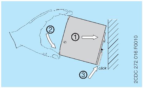
Mounting
The switch mode power supply can be snapped on a DIN rail (TH 35-15 or TH 35-7.5 according to IEC/EN 60715) asshown in the accompanying picture. For that the device is set with its mounting rail slide on the upper edge of the mountingrail and locked by lifting it downwards.
Demounting
Remove the switch mode power supply as shown in the accompanying picture. For that the latching lever is pulleddownwards by means of the screwdriver. Alternatively you can press the unlock button to release the device. Then in bothcases the device can be unhinged from the mounting rail edge and removed.
Mounting position
The devices have to be mounted horizontally with the input terminals on the bottom. In order to ensure a sufficientconvection, the minimum distance to other modules should not be less than 25 mm (0.98 in) in vertical and horizontaldirection.
[B][A]
|
L1 L2 L3 |
CP-T24/20.0 |
||||||||
|
L1 L2 L3 |
PWM |
L+ L+ L- L- |
|||||||
[B]
L+L+L- L-
[A]
Data sheet | Power supply CP-T 24/20.0 – 3
Electrical connection

![]()


L+, L- Output voltage
13 14 L+ L+ L- L-
|
L1 L2 L3 |
PWM |
L+ L+ L- L- |
L1, L2, L3 Input voltage 13-14 Signalling contact |
||||||
|
o o L1 L2 L3 |
o Protective earth |
||||||||
Connection diagram
Preparations:
– Connect to main according to the specific national regulations.
– Power supply cables and unit must be sufficiently fused. A disconnecting device has to be provided for the power supply to disengage unit and supply cables from supply mains if required.
– We recommend to choose the cable section as large as possible in order to minimize voltage drops.
– In order to ensure sufficient air-cooling the distance to other devices has to be considered.
Instructions:
1. Connect the input terminals L1, L2 and L3.
2. Connect the protective earth conductor to the terminal o (protection class I).
3. Provide a suitable disconnecting device (e.g. line protection switch) in the supply line acc. to IEC/EN 60950.
4. Rate the lines for the maximum output current (considering the short-circuit current) or provide a separate fuse protection. The input side is protected by an internal input fuse.
5. Observe the polarity.
The device is overload, short-circuit and open-circuit proof. The secondary side of the power supply unit is electricallyisolated from the input and internally not earthed (SELV) and can therefore be earthed by the user according to the needswith L+ or L- (PELV).
Operation
DANGER!
High current
Risk of electric arcs and electric shocks!
► Do not modify the installation (primary and secondary side).
► Intended use.
CAUTION!
Depending on the operation conditions the enclosure can become very hot
Risk of burns!
► In order to ensure sufficient air-cooling the distance to other devices has to be considered.
The device is intended for use as a primary switch mode power supply. Any other usage is not supported by themanufacturer. Other usage may impair safety and cause operational difficulties or destruction of the unit.
Service
The internal fuse is not user-replaceable. If the internal fuse blows, most probably the device is defective. In this case, anexamination of the switch mode power supply by the manufacturer is necessary.
4 – Power supply CP-T 24/20.0 | Data sheet
Technical data


Data at Ta = 25 °C, Uin = 3 x 400 V AC and rated values, unless otherwise indicated
Input circuit – supply circuit L1, L2, L3
Rated input voltage Uin 3 x 400-500 V AC
Input voltage range 340-575 V AC
480-820 V DC
Frequency range AC 47-63 Hz
Typical input current 1.1 A
Typical power consumption 538 W
Inrush current limiting 20 A
Power failure buffering time min. 20 ms
Internal input fuse per phase T3.15 A / 500 V AC
Recommended backup fuse 3 pole miniature circuit breaker ABB type S 203
characteristic B or C
max. rating 20 A
Power factor correction (PFC) yes, passive, 0.65
Discharge current towards PE < 3.5 mA
input / output < 0.25 mA
Indication of operational states
Output voltage OUTPUT OK: green LED output voltage OK
OUTPUT LOW: red LED output voltage too low
Output circuit L+, L+, L-, L-
Rated output power 480 W
Rated output voltage 24 V DC
Tolerance of the output voltage 0…+1 %
Adjustment range of the output voltage 22.5-28.5 V DC
Rated output current Ir Ta ≤ 60 °C 20 A
Derating of the output current 60 °C < Ta ≤ 70 °C 2.5 %/°C
Signalling contact for output voltage OK 13-14 solid-state (max. 60 V DC, 0.3 A)
threshold 17.6-19.4 V
insulation voltage 500 V DC
Mininum fuse rating to achieve short-circuit 13-14 M 60 V DC, m 0.3 A fast-acting
protection
Maximum deviation with load change statical ±1 % (single mode)
±5 % (parallel mode)
change of output voltage within ±0.5 %
the input voltage range
Control time at rated load < 2 ms
Starting time after applying the supply voltage at Ir max. 1 s
with 7000 µF max. 1.5 s
Rise time at rated load max. 150 ms
with 7000 µF max. 500 ms
Fall time max. 150 ms
Residual ripple and switching peaks BW = 20 MHz 100 mV
Parallel connection configurable, to increase power, up to 2 devices,
min. 0.1 Ir – max. 0.9 Ir
Series connection yes, to increase voltage, max. 2 devices
Data sheet | Power supply CP-T 24/20.0 – 5
2CDC114069D0201