
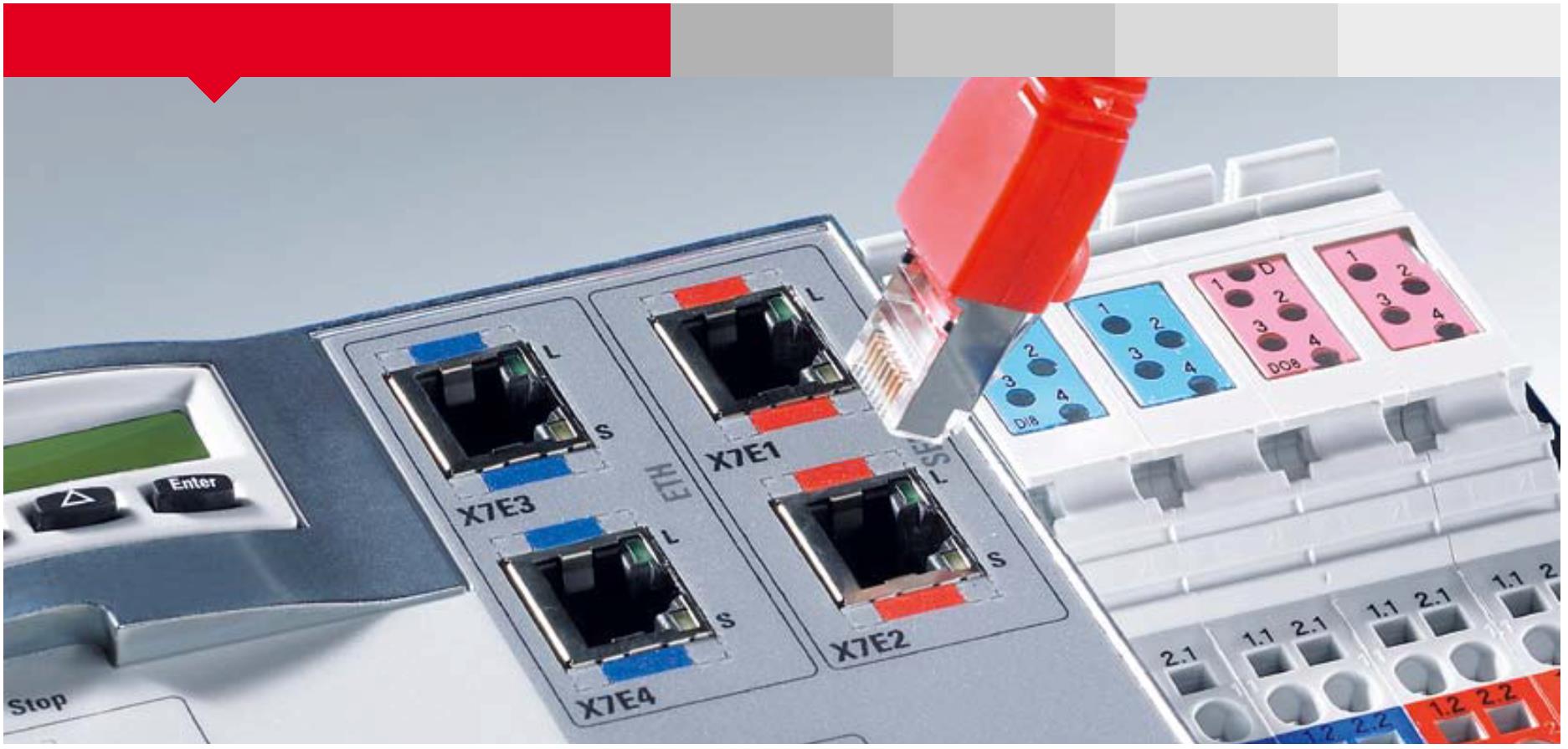
plug and play – Sercos,the automation bus
![]()


Sercos III I Introduction Advantages and benefits I Sercos III

![]()
![]()


Advantages and benefits at a glance
Mechanical engineers and users benefit froma wide range of advantages and benefits:
Proven Reliable
|
■ Sercos is an open, international standard ■ |
■ Redundant data transmission ensures high machine ■ |
(IEC 61784, IEC 61158, IEC 61800-7). and plant availability.
|
■ Complete backwards compatibility ensures that ■ |
■ Synchronization which is accurate to less than one micro- ■ |
it is a long-term investment. second ensures deterministic and synchronized communica-
|
■ Leading suppliers of automation systems back Sercos ■ |
tion across the whole Sercos network. |
|||||||
|
with broad product portfolios. |
■ Sercos allows fail-safe communication: ■ |
|||||||
|
■ Sercos technology is widely accepted in many industries, ■ |
Cable breaks are recognized within 25μs which means |
|||||||
in particular for high-end applications. that data is lost for a maximum of one cycle.
|
■ More than four million real-time nodes are currently being ■ |
■ Robust cables made from copper or fiberglass. ■ |
used in more than 500,000 applications – and the numberis growing every day.
Economical
|
■ Ethernet-standard IEEE 802.3 physics and protocol ■ |
■ Sercos energy: save energy and maximize productivity ■ |
are used. at the same time.
■ Machine controls can set components to idle mode.
■
|
Sercos – the automation bus: one of the leading bus systems for applica- tions in industrial sectors for over 20 years. The real-time technology with |
Simple ■ Sercos devices are easy to configure and put into use. ■ ■ The cables are easy to connect as neither the physical ■ |
■ Fast and efficient data transmission allows for shorter ■ cycle times and a higher output. |
|||||||
|
its millionfold proven quality, the universal application possibilities and high security of investments make the Ethernet system the first choice in |
order of the devices nor the order of the connection to the two Sercos ports is important. ■ Maintenance is easy because the devices and their position ■ |
Flexible ■ Flexible network topologies (ring, line, star/tree structures). ■ ■ Comprehensive choice of device profiles for all types ■ |
|||||||
|
mechanical engineering and construction. |
within the topology are recognized automatically. |
of automation devices. ■ Innovative communication functions, for example direct ■ |
|||||||
Fast
cross communication and ring redundancy.
■ High speed due to the use of Fast Ethernet
■
(100Mbps full duplex).
Safe
|
■ Short running times: the summation frame procedure, ■ |
■ Safety functions up to SIL3 that are in accordance with ■ |
the on-the-fly processing and the direct cross communica- IEC 61508 can be implemented with CIP Safety in Sercos.
|
An efficient and deterministic communication protocol |
This creates a basis upon which devices from different tion reduces running times in the network to a minimum. |
■ Safety-relevant and non-safety-relevant data is transferred ■ |
||||||||||||
|
based on an optical transmission system not susceptible |
manufacturers can be combined without any problems. |
■ Configurable cycle time:The communication cycle ■ |
over the same cable. |
|||||||||||
|
to interference is the foundation for Sercos’ success; today Sercos® is used successfully in the most varied |
Today, over 4 million real-time nodes are being used on a daily basis in over 500,000 applications. |
can be set between 31.25μs and 65ms – synchronization accuracy << 1µs. |
■ Devices can securely communicate outside of network ■ boundaries thanks to CIP Safety’s routing capability. |
|||||||||||
|
sectors and applications. Sercos has established itself as the de facto standard on all large automation markets |
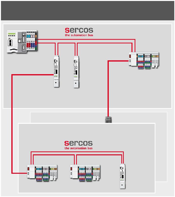
Sercos III – universal communication for distributed |
Efficient ■ Hot plugging can be done without damaging real-time ■ |
Independent ■ Sercos technology is independent from manufacturers. ■ |
|||||||||||
when dealing with challenging applications that place automation solutions
or synchronization characteristics. The user organization Sercos International e.V.
|
great demands on dynamics and precision. However, |
Industrial automation requires real-time-enabled and |
■ Optimized use of bandwidth through a summation frame ■ |
owns all rights to Sercos technology. |
||||||||||
|
Sercos does not only specify a real-time-enabled com- |
manufacturer-independent communication solutions. |
procedure and multiplexing procedure. |
■ Specifications are maintained and developed ■ |
||||||||||
|
munication system, but goes a lot further and specifies over 700 standardized parameters which describe the interaction between control systems, drives and other |
Different kinds of automation devices must be able to be easily and universally connected.The open, IEC consistent universal bus for Ethernet-based real-time |
■ All Ethernet-based protocols (including TCP/IP communica- ■ tion) can be transmitted with real-time data at the same time using the same cable. |
by a task force which covers all manufacturers. ■ All specifications are freely available. ■ ■ You do not have to be a member to use Sercos technology. ■ |
||||||||||
peripheral devices using universal semantics. communication, Sercos III, meets these demands today
with a wide variety of benefits.
02 03
Sercos III I Basic principles / concepts Basic principles / concepts I Sercos III

|
Basic principles / concepts |
Universal communication from the office to the field level via Ethernet |
Internet |
Company network
Intranet Router Office
|
Factory network |
Sercos III + Ethernet |
Router |
Service |
|||||||
|
Facility network |
Control system |
|||||||||
Router
Machine network
Master Master
Periphery Drive I/O Periphery
|
Gateway Safe I/O |
Safe drive Drive |
Field bus Service
|
Why Ethernet? |
EEtthheerrnneett SSeerrccooss IIIIII ++ EEtthheerrnneett |
||||||||||
|
Ethernet makes it possible to have a single network infrastructure for com- munication across all levels of the automation pyramid. The vertical integra- tion of anything from sensors to accounting software opens up new pos- |
Without particular specifications, Ethernet cannot satisfy real-time demands and efficiency requirements in auto- mation engineering. It is for this reason that appropriate transmission procedures have to be defined which make |
evaluate and compare how different real-time Ethernet solutions work and what effects they produce. In the end, an objective comparison of the solutions can only be made when actual application scenarios are available. |
|||||||||
|
sibilities for operational control. At the same time, modern Ethernet-based networks allow for greater flexibility when installing and expanding control topologies within the production chain when compared with conventional the Ethernet efficient and compatible with real-time. Such diversity in real-time Ethernet solutions available on the market does not make it easy to keep perspec- |
What is important is to understand the basic principles of different real-time Ethernet solutions and how they work. |
||||||||||
field buses.
tive. Even specialists sometimes find it difficult to fully
|
Ethernet technology provides a tangible range of benefits: ■ recognized and future-proof technology ■ ■ many times higher data throughput than field buses ■ ■ no proprietary hardware required ■ ■ use standard readily available components such as ■ double shielded CAT5e copper cables, connectors and controllers ■ flexible and compatible automation systems thanks to ■ international standards |
■ universal IT concepts with an integrated transmission ■ medium and transmission protocol from the office to the field level ■ can connect to global networks for diagnostics ■ and maintenance Ethernet technology combines peripheral, driver, safety and office communication in one common medium – simple, economical and efficient. |
? ? ? ? ? ? FL-net Profinet Mechatrolink III Drive-Cliq ? JetSync Sercos EtherNet/IP CC-Link IE EPA Powerlink Vnet/IP Varan TTEthernet RTnet SynUTC HSCI Modbus RTPS ? PowerDNA ? Fast Track Switching SafetyNET p Ethercat RAPIEnet TCnet SynqNet AFDX Switch with time server RTEX DART-EC Compatibility of real-time Ethernet protocols |
04 05
Sercos III I Basic principles / concepts Basic principles / concepts I Sercos III
![]()
![]()

protocols shown in the image are commonly carried out for a precise time base that is not affected by transmis-
Cycle times Synchronization required
in specific hardware, not only the version in the right sion time and time fluctuations in the communications
Standard Ethernet communication Not cyclical Not synchronized figure. medium. However, since the time base is not able to en-
sure any determinism when transmitting data, the data
|
Positioning drives, frequency converters, I/O periphery |
4 – 10 ms > 4 ms |
Protocol efficiency In automation engineering, many users that each have a |
always has to be transmitted long enough in advance so that it is available to be processed when it is time for |
||||||
|
Drives with peripherals signal processing, high-speed I/O periphery |
250 µs – 4 ms << 1 µs |
low amount of data to transmit are typically connected to each other via control and sensor/actuator levels. If |
synchronization. |
||||||
|
Central drive concepts, highly dynamic metrology applications |
31.25 µs – 125 µs << 1 µs |
this process data is transmitted in individual telegrams, an unfavorable ratio between the Ethernet overhead and |
Separate clocks are also used in some real-time Ethernet protocols to minimize jitters during cyclical transmission. |
||||||
Comparison of real-time requirement categories
the user data volume will be created. In addition, should
the user data be less than 46 bytes, telegrams are filled Topology All standardized real-time Ethernet solutions are listed in net due to full duplex transmission and point-to-point
with zero bytes (called padding) to reach the minimum Star topology, which is commonly used for EthernetIEC 61784 Part 2; each of the protocol specifications for connections. However, additional lag times and non-
length of 64 bytes. In doing so, valuable bandwidth is connections, is avoided wherever possible in automa-real-time Ethernet solutions is contained in IEC 61158 deterministic delays during high-peak periods have been
not used. For this reason, summation frame telegrams, tion engineering since it requires more wiring. Automa-series of standards.The different kinds of technology recorded when using switches.
where real-time data from several users is consolidated tion devices are better when directly connected, thatdescribed there have Ethernet IEEE 802.3 in common as
their transmission medium and protocol.This technology Real-time Ethernet:
into one common telegram, are more efficient. is, without external infrastructural components instead
covers the whole plant and process automation sector standard hardware vs. specific hardware
(“Daisy Chaining”).This ensures that hubs or switches
Lag time/cycle time are integrated into terminal devices. In the case of ex- in terms of how it can be applied. When it comes to Different processes can be used to make Ethernet
A deterministic transmission time (lag) preferably tensive machines and plants, it can be advantageous toperformance and real-time, the greatest demands are compatible with real-time.The simplest form of real-time
with a lower jitter is required (motion control applica- add a branch line or a transmission line to one or moreplaced on bus systems which are used in motion control protocol is placed above theTCP/IP layer and is based
tions <1 µs) for real-time communication. Processing devices, or to create a tree or star topology with externalapplications. on a polling mechanism, or time slot process (image
times can be reduced by removing network infrastruc- infrastructural devices or with a device integrated logicbelow, left). Real-time protocols in which conventional
Determinism protocol stacks (layers 3+4, transfer and network layer)
ture components (switches, hubs) and by processing system that has additional ports.
telegrams through network devices by the network us- Standard Ethernet is not real-time-enabled because it is are used in real-time protocol (image below, center) are
ers during the cycle. Cycle times of well under 1 ms can not deterministic.The lack of determinism is due to the more efficient. Further increase in performance is pos-
be achieved with more efficient protocols and a faster fact that while information collisions are indeed flagged sible by processing protocols in hardware (image below,
processing time for telegrams at individual network in traditional CSMA/CD processes, they are, however, right). Some real-time Ethernet protocols use their
nodes. not avoided.This results in there being considerable own Ethernet frame format at the same time and are
fluctuations in the time when transmitting information. therefore only compatible with Ethernet on the physical
Synchronization processes Admittedly, collisions are avoided in switched Ether- layer. On the basis of performance, all real-time Ethernet
Automation systems located in different places can be
synchronized in different ways.
Application Application Application
During a time slot process, synchronization can be
Real-time protocol deduced from the cyclical protocol.The synchronization
|
TCP |
Real-time UDP TCP UDP TCP UDP protocol |
Real-time protocol |
process is based on the transmission of a synchroniza- tion signal which is cyclically received and analyzed by all |
network devices. In order to be able to ensure the best
IP IP IP
possible synchronization, the signal has to be sent and
MAC MAC MAC received within a strict time period with the lowest pos-
Ethernet Ethernet Ethernet
sible time discrepancy. PHY
PHY PHY
EtherNet/IP, Modbus/TCP Powerlink, Profinet RT Sercos III, Profinet IRT, Ethercat
Another way of increasing the Ethernet’s temporal Protocol efficiency
precision and synchronization is based on the principle
|
Cycle time |
of separate clocks (IEC 61588) which are synchronized with each other via telegrams. Separate clocks allow |
Concepts of different real-time Ethernet solutions
06 07
Sercos III I Sercos mode of operation Sercos mode of operation I Sercos III
![]()
![]()


|
Sercos mode of operation |
With Sercos, real-time data is sent to IEEE 802.3 in cyclical telegrams with Ethernet protocol type 0x88CD. |
Given that additional network infrastructure compo- nents (such as hubs or switches) are avoided, trans- |
These make M/S, DCC and SVC, SMP and Safety com- mission times are reduced to a minimum throughout
munication mechanisms available.The replaced data is the network.
addressable via standardized functional groups, classes
and profiles. Subsequent communication mechanisms are available
in the real-time channel:
|
Sercos differentiates between the following |
■ M/S (Master/Slave): Exchange of functional data ■ |
kinds of telegrams: between masters and slaves in an M/S connection.
|
■ Master Data Telegram (MDT):The master sends ■ |
■ DCC (Direct Cross Communication): direct cross ■ |
schedule data to the slave devices. communication between devices in a DCC connec-
|
■ AcknowledgeTelegram (AT): The slaves send their ■ |
tion, either between control systems or between any |
status data to the master and to other slave devices. periphery slaves (e.g. drive, I/O, camera, gateway).
■ SVC (Service Channel): Exchange of service data that
■
The connected devices are recognized in the initialization is based on demand in a SVC channel as a component
phase (phase start-up with communication phases CP0 in real-time communication.
|
– CP4), they are addressed and configured for applica- |
■ SMP (Sercos Messaging Protocol):Transmitting ■ |
tion. Each slave is assigned a device channel in the MDT functional data from several devices in one time slot
and the AT, which the slave either uses to read from or by using a multiplex process configured in an M/S
to write into. Depending on the amount of data, several or DCC connection.
|
MDT and several AT are sent by the master per commu- |
■ Safety: Exchange of safety-related data in a M/S ■ |
|||||
|
In order to fully meet the demands of modern industrial automation, Sercos provides a high performance protocol. This protocol combines |
nication cycle.The telegram transports data from device to device.The relevant schedule data is read at each device or the required status data is written in. |
or DCC connection, e.g. disabling or approval signals or other set values. ■ Sync: Cyclical synchronization trigger for precise, ■ network-wide synchronization |
||||
the openness of standard Ethernet with the need for real-time accuracy
Real-time channel
in automation engineering.
Sercos telegrams that are in the real-time channel are
processed on the fly via individual network devices dur- “Years of positive experience usinging the cycle.The telegrams are therefore only delayed Sercos control systems and drives
Transmission principle telegrams (Ethertype 0x88CD) are transmitted through by a few nanoseconds because the whole protocol led us to install Sercos as a system
a real-time channel that is free of a risk of collision. process is carried out in hardware. In this way, network bus for our machines and plants.Thanks to Sercos communication is based on a time slot pro-
Parallel to this real-time channel, a UC channel can performance is independent of protocol stack, CPU Sercos’ real-time performance for motion, cess with a cyclical transmission of telegrams that
be configured, in which all other Ethernet telegrams performance or software implementation transmission safety, vision and I/O as well as the pos- are based on a master slave principle. Cycle times
(Ethertype <> 0x88CD) and IP-based protocols such as times. sibility of integratingTCP/IP services easily, are 31.25 µs, 62.5 µs, 125 µs, 250 µs as well as many
TCP/IP and UDP/IP can be transmitted.These time slots cabling and engineering was made consid- times over 250 µs up to a maximum value of 65 ms.
are called UC channels. erably easier.” Besides automation concepts with centralized signal
processing, decentralized automation solutions are
also created as a result of this bandwidth during cycle Cycle times and the division of the bandwidth or bus
times. In order to meet hard real-time demands despite cycle in the real-time and UC channels can be adjusted
Application
Customer solution
|
using Ethernet, a communication cycle is divided into two time slots (channels). Sercos-defined real-time |
for each application. |
Application level |
Encoder profile Safe Motion Drive profile Safe Drive I/O profile Safe I/O Safety M/S SVC DCC Sync |
Ethernet application
IP |
||||||||||||||||||||
|
MDT 0 |
MDT 1 |
MDT MDT
AT AT Ethernet 2 3 2 3 telegrams Real-time channel (RTC) UCC |
MDT 0 |
RTC = Real-Time Channel UCC = Unified Communication Channel MDT = Master DataTelegram AT = AcknowledgeTelegram |
Communication level Hardware level |
Sercos III communication controller Duplex Fast Ethernet (100 MBit/sec) |
||||||||||||||||||
Configuration of the Sercos communication cycle Communication mechanisms in the real-time and UC Channel.
08 09
Sercos III I Sercos mode of operation Sercos mode of operation I Sercos III
![]()
![]()


|
UC Channel Conventional Ethernet communication is synchronized in the so-called Unified Communication Channel (UCC) in the Sercos network, e.g. for e-mail, web services or other proprietary and standardized Ethernet-based pro- tocols.This channel sets itself down onto the Ethernet- layer without tunneling and has a range of benefits: ■ it is possible to test and configure slaves even without ■ |
“The option to communicate di- rectly via standard Ethernet proto- cols using all devices even without constant Sercos real-time communication. makes the set-up operation easier. It also allows us access to the device parameters while the operation is running.” |
Topology Sercos networks consist of a master which coordinates and at least one slave which carries out automation functions. Generally, the devices are ordered simply and neatly in line or ring topologies. For this purpose, each Sercos device has two communication connections which are connected to the previous and subsequent device via an Ethernet cable – either using a twisted |
“Sercos has a clear and robust data structure.This increases operational reliability and simplifies applica- tion development.The network status is always clear and entirely transparent. I can make diagnoses of my plant on each net- work node with current Ethernet diagnosis tools.” |
initializing real-time network and master hardware two-wire line (twisted pair) or an optical fiber. As a result
|
■ connection to other automation devices which support ■ |
of full duplex-enabled Ethernet technology, a logical ring |
In a line topology, the master is positioned at the |
another Ethernet-based protocol which is not Sercos appears in a line topology and a logical double ring ap- beginning of a line or between two lines.The telegrams
|
■ directly addressing Sercos devices via MAC or ■ |
pears in a ring topology (see image). |
containing data run through the slaves and are ‘looped |
an IP address Protocol structure back’ by the last device. All devices analyze the data
|
■ standard Ethernet devices such as laptops are ■ connected directly to Sercos devices via any free |
Sercos telegrams contain a Sercos header and a data field embedded in the Ethernet frame |
Line structure (Individual ring) |
Ring structure (Double ring) |
running in both directions so that all data is guaranteed to reach each device within the cycle independent of the |
||||||||||||
|
Sercos port ■ full processing power for the application because the ■ |
(see image below). |
Master Master |
order they are placed in (➝■see direct cross communica- tion). In this way, all devices can be integrated into the |
|||||||||||||
|
master does not have to tunnel or fragment Ethernet packets |
The Sercos header describes which phase the network is in and the position of the MDT and AT telegrams in the communication cycle.The MDT and AT data fields |
M1 M2 M1 M2 |
network, even across long distances, e.g. assembly lines, without high installation costs. |
|||||||||||||
S/IP protocol consist of three areas: By adding an additional cable, the Sercos network
|
The S/IP protocol allows data to be exchanged in one |
■ hot plug field: exchanges data with slaves that ■ |
closes to form a ring; a line is added between the last |
cycle using any Sercos devices without requiring a have been linked to the network while the operation slave and the master, or two lines between the last
Sercos master or constant Sercos communication.The is running. slaves.The master feeds the ring in opposite directions
|
S/IP protocol can also be used in a cyclic real-time opera- tion. In this instance, the S/IP telegrams are transmitted |
■ service channel field: total number of communication ■ channels that exchange acyclic data between master |
Slave 1 |
Slave 2 |
Slave n |
Slave 1 |
Slave 2 |
Slave n |
over both ports so that the data is also analyzed in two directions in the ring. Besides having all the benefits |
With hardware redundancy Without hardware redundancy
through the UC channel without negatively interfering and slaves. of a line topology, ring topology provides additional
|
with the network’s real-time process. |
■ real-time data field: is used to create acyclic, cyclic or ■ |
Sercos-based topologies: Line and ring |
redundant cabling.This means that a break in the ring |
clock-synchronous connections, and so also real-time
communication between any devices in the Sercos
|
network. |
Realization of a branch via an external infrastructural component |
Realization of a branch via ports integrated in the device |
|||||||
|
Telegram length: 84 – 1538 Bytes (protocol management: 44 Bytes) Telegram time: 6,8 – 123,1 µs |
Switchboard A Switchboard A |
||||||||
40…1494 Bytes
Master Master
|
Ethernet package |
Ethernet header |
Sercos III header |
Data field Checksum |
Slave 3 Slave 3 |
|||||||||||||||
|
Sercos III data field |
Hot plug field (new devices) |
Service channel field |
Real-time data field |
Slave 1 |
Slave 2 |
TopoExtensions |
Slave 1 |
Slave 2 |
TopoExtensions |
||||||||||
Switchboard C Switchboard C TopoExtension TopoExtension
Switchboard B Switchboard B
TopoExtension
|
Real-time data field with standard (M/S) and lateral communication connections (DCC) |
M/S connection device #1 |
M/S connection DCC connection … device #N device #1 … |
DCC connection device #N |
|||||||||||||||||
|
Device data |
Standard data |
Safety data container |
Slave 4 Slave 5 Slave 4 Slave 5 |
Slave 9 Slave 6 |
Slave 4 Slave 5 Slave 4 Slave 5 |
Slave 9 Slave 6 |
||||||||||||||
Sercos telegrams with a clear data structure for greater operational reliability and easy development. Extended topologies with branches or stubs.
10 11
Sercos III I Sercos mode of operation Sercos mode of operation I Sercos III

![]()


|
can be compensated for without losing synchronization or causing a breakdown in communication (➝■see ring redundancy). Single devices or machine modules can also be con- nected to a line or ring via a branch line or a transmission line. To achieve this, either an infrastructural component with the appropriate branch line ports is integrated into the network or this function is directly integrated into the Sercos device. |
“With Sercos, we can adjust the network very easily to our cur- rent machines and plant structure. The fact that switches and hubs are not required means that installation costs are reduced and cabling is made considerably easier.” |
Sercos also supports hierarchical, cascading network
structures. At the same time, individual network seg-
ments are connected to each other via Sercos allowing
network structures to be created which are connected Ethernet devices (e.g. notebooks) to a Sercos real-time
in real-time and that are completely synchronized. Cycle network.This means that every Ethernet and IP protocol
times in single segments can be different, e.g. 250 μs on Sercos devices can be accessed without interfering
for connecting drives and fast I/Os, and 2 ms for con- the Sercos network real-time process (online mode),
necting control systems. Devices across the entire and without needing the Sercos protocol to be activated
network can communicate with each other in real-time. (offline mode).
Moreover, all devices across the entire network are guar-
anteed to be synchronized. Field bus integration
Automation devices which (still) do not have a Sercos in-
Hard and soft master
terface can be integrated into the Sercos network by us-
When it comes to masters, either specific hardware (or ing the appropriate gateways. Communication gateways
hard master) or an alternative standard Ethernet control- are available for the coupling of field buses for example
ler (or soft master) can be installed. In soft masters, (e.g. Profibus, CAN), encoder interfaces (e.g. SSI) or
Sercos-specific hardware functions are relocated to sensor/actuator bus (AS-i, IO-Link). Moreover, gateways
the hardware-related and real-time capable part of the with axis controller periphery are available to integrate
master driver, so that the master-related activation can analogue axes. Gateways are either a feature of Sercos
be realized completely in software.This form of master devices (e.g. modular I/Os) or are connected to the Ser-
realization is interesting for PC-based controlling plat- cos network as separate devices.
forms for example.
Sercos Slave
Wiring
Installing a Sercos network is very easy and does not
Gateway
require any infrastructural components such as switches
Field bus master
or hubs. All devices are connected directly to each other
via patch or crossover cables. Fast Ethernet technology
|
means that a 100m wire can be strung between two devices.The Ethernet ports on the devices are inter- |
Field bus Slave 1 |
Field bus Slave 2 |
… |
changeable and can even be used to connect standard
12 13
Sercos III I Sercos operating principles Sercos operating principles I Sercos III

![]()
![]()


|
Sercos operating principles |
How it works: Given that real-time telegrams are always processed in two directions independent of the kind of topology, a direct exchange of data between any given slave is en- abled within the communication cycle (see image).This has the advantage that data can always be transmitted |
“The possibility of cross communi- cation means that decentralized au- tomation solutions can be installed with minimal reaction times and a great amount of flexibility.” |
between the slaves within an individual communication
cycle while causing minimal delay, even with increased
cycle times. Moreover, all real-time data is available syn-
chronized – that is, in relation to the general communica-
tion cycle – at every point in the network. As a result,
data can be processed extremely easily, efficiently and
flexibly at individual network nodes. Network diagnosis
and monitoring can also be carried out as a result.
Direct lateral communication forward
Tx Rx Tx Rx Tx Rx Tx
Master Slave Slave Slave
Rx Tx Rx Tx Rx Tx Rx
Direct lateral communication backward
Direct cross communication in a line topology Cross communication – Sercos allows for decentralized intelligence and
an unlimited capacity to work in real-time because direct communicationbetween all devices is possible. Indirect communication between slaves by
|
bypassing the master would compromise synchronous movements, e.g. by corrupting gantry axes or slowing down reaction times, e.g. when transmit- ting a trigger signal quickly. Sercos slaves can communicate via cross com- munication directly and with a minimum of communication dead times – Synchronization Sercos defines how the actual value is recorded and how valid the set value is for processes from different products and manufacturers that are to be synchronized. Each device receives a data telegram with a particular |
“Increased accuracy of the transmis- sion ensures that we can implement the most challenging applications.” |
|||
|
this ensures unlimited real-time communication and intelligent automation structures. Control systems use the same principle to directly communicate with each other. transmission time delay that is appropriate to the device. Unlike other Ethernet bus systems, Sercos derives a general execution time directly from the bus. The device calibrates itself independently with the bus cycle by us- |
||||
ing the arrival of the MST while taking into account the
transmission time in the bus during each bus cycle to
|
DCC – Slave-to-Slave C2C – Controller-to-Controller |
C2C DCC DCC |
generate and adjust the internal synchronizing mecha- nism. As a result, separate clocks are synchronized |
|||||
|
HMI HMI HMI Master Master Master |
exactly without exchanging time data that overloads the bandwidth. |
||||||
The Sercos master simply has to detect the line or ring
transmission time and transmit data to each device to-
gether with a sum value that has been appropriately con-
|
DCC DCC |
figured. Variations in the sum value can delay the stable synchronization signal. Hence delaying the synchroniza- |
Cross communication between slaves and control systems
14 15
Sercos III I Sercos operating principles Sercos operating principles I Sercos III
![]()
![]()


tion time or having to reconfigure the sum value, for Given that communication continues when there is a Oversampling and time stamping In Sercos telegrams, however, up to 1,494 bytes of all
example, can be prevented when connecting additional break in the cable, if necessary, new devices or groups The oversampling process which is integrated into device user data is packed together with an additional
devices to the Sercos network which is operating in of devices can be connected to the network while it is in Sercos protocol allows more than one nominal/actual 44 bytes of overheads. With packets that are a maxi-
cyclical real-time (so-called “hot plugging”).The synchro- operation, and can be integrated into the communication value per cycle to be transmitted.This increases the deli- mum size of 1,538 bytes, the bandwidth available for
nization process ensures that cyclical and simultaneous (so-called hot plugging or hot swapping).The system cate nature of the process control in extremely critical productive data increases to up to 97%.
synchronization of all connected devices is carried out can merge seamlessly and without interference into the laser applications, for example, because more data can
|
independently of topology and of the quantity of devices in Sercos networks.The process itself is quick, robust |
configured operation. |
be consolidated and emitted. |
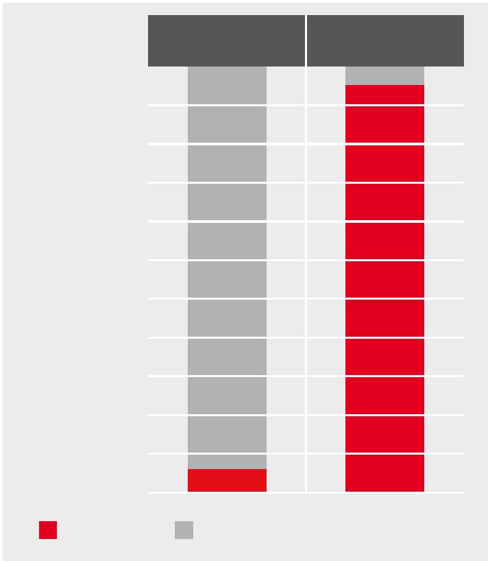
Polling of individual IP packages |
Sercos III telegram |
and simple to apply. Time stamping also opens up new opportunities for
100%
communication across the fixed cycle.This function
90%
|
Using the described process, Sercos is able to achieve synchronization accuracy of less than 20ns and syn- chronicity of less than 100ns. Given that individual |
transmits event-controlled results such as specific measured data and switches outputs independent from the cycle.This increases the stability of the process in |
80% 70% |
60%
Sercos networks can be connected to a network system complex processing solutions, like those in the semicon-
based on a C2C profile (C2C=Controller to Controller), ductor industry.
50%
|
fully synchronized network structures can be formed 40% without limiting synchronization performance. Performance 30% Custom Ethernet protocols from office technology rely Ring redundancy and hot plugging on user data being sent as individual packets to each A network in a ring topology which is safe from inter- ference is still operative when a cable breaks or when slaves are connected or disconnected (hot plugging) and no interruption is caused. All devices remain connected to the master when a cable breaks due to the additional cable in a ring network.The Sercos connections on the |
“A Sercos hardware failure or break in a cable does not result in a breakdown in communication. Instead, we are able to replace defective devices or cables while the system is in operation, which significantly increases machine availability.” |
20% |
10%
device – embedded in a defined framework made from
protocol overheads.The quantity of overheads in data
0%
traffic is disproportionately high in small user data pack-
User data Protocol management
ets such as simple setpoint targets. A simple example of
|
how to use fast Ethernet bandwidth efficiently: if status data of 4 bytes per device for 20 devices were sent indi- |
Efficient use of bandwidth with Sercos |
slaves at the breakage point switch to two separate lines vidually, that would take up 1,680 bytes = 20*84 bytes
|
with “loop back” without causing any delay. The recon- figuration time takes a maximum of 25μs so that at the very most the data transmitted from one cycle is lost. The breakage point can be located exactly and defective cables can be simply exchanged while the operation is running. |
altogether (smallest packet size with Ethernet: 64 bytes). However, only 80 bytes would be used productively for the application – that’s approx. 5% of the bandwidth, even during low-peak cycle times. |
“Sercos’ efficient real-time proto- cols result in universal, consistent machine connection with fast reac- tion times and great accuracy.” |
|||||||||||||
|
Cycle time in µs |
Cyclic data per device in bytes |
Maximum number of devices (without UCC) |
Maximum number of devices (with UCC, 250 Bytes = 20 µs) |
Maximum number of devices (with UCC, 1,500 Bytes = 125 µs) |
|||||||||||
31.25 8 7 2 –
HMI
62.5 12 14 8 – Master Master
125 16 26 21 –
Ring Line 1 Line 2 250 12 61 57 30
250 32 33 31 17
500 12 122 120 94
Slaves Slaves 1,000 50 97 95 85
1,000 32 137 134 120
|
Uninterrupted switching (loop back) to line topology in the case of hot plugging oder cable break |
Additional cable connects two line topologies to create a ring topology |
1,000 12 251 245 220 |
Ring redundancy and hot plugging Example configurations
16 17
Sercos III I Function-specific profiles Function-specific profiles I Sercos III

![]()
![]()


|
Function-specific profiles |
Cyclic real-time data in one connection |
Sercos real-time communication with stan- dardized parameters, using the example of the drive profile |
2 Byte 4 Byte 4 Byte
Binary Decimal signed Decimal unsignedS-0-0012 Warning
S-0-0050
S-0-0051 Position actual value
S-0-0100 P-gain in speed control
S-0-0101
…
Parameter for device Selected parameters for concrete application
|
Device description Sercos offers the possibility to represent all types of automation devices on the field and controlling level in the different phases of their life cycle in a functional and logical manner. The device description language SDDML was developed in order to describe devices and the provided functions for the offline configuration Device models and profiles and for their easy display in a generic engineering tool. |
“We have made very good experi- ences with the excellent degree of standardization of the drive profile whereby it was possible for us to integrate devices of various manufacturers to our control and to commission the machine in a remarkably short time. |
||||||
|
The device model from Sercos not only supports pure automation devices but also hybrid devices which combine various applications in one device. It is for this reason that no device profiles but, instead, function-specific A configuration interface (SCI) determines the network configuration and defines which slaves must be present and which are optional.The slave devices are identified via criteria which are described in the file. Furthermore, |
|||||||
|
profiles are defined by Sercos. |
the configuration file describes the parametrization of the individual devices by means of a generic procedure. In addition, the parametrization of the master can be carried out. |
||||||
FDT/DTM for Sercos
Sercos makes use of the open and manufacturer-inde-
pendent FDT technology to standardize the communica-
Simplified processes – from engineering The following profiles have already been specified: The parameters of the different profiles are either con-
tion between field devices and software engineering
|
■ Generic device profile: functions for diagnosis and ■ |
figured into the real-time telegrams for cyclical transmis- |
tools. It is for this purpose that device manufacturers |
to maintenance |
may deliver a Sercos device with a DTM (Device Type The configuration, startup, diagnostics and maintenancemanagement functions in all types of devices sion or these parameters are accessed via the service
|
■ Drive profile: consistent and continuous functions for ■ |
channel or the S/IP protocol. |
Manager) adjusted to the device. In this case, the DTM |
of Sercos networks is quite simple.The user can focus |
is directly integrated into the corresponding framework on the application – Sercos manages the network andcontrolling of hydraulic, pneumatic and electric drives
|
■ I/O profile: consistent and continuous functions for ■ |
application. However, an SDDML-conforming device de- |
supports the user in startup and diagnostics. All devices |
scription file can also be converted into a corresponding are connected with industry-compatible standard CAT5econtrolling of modular and non-modular I/O stations
|
■ Encoder profile: consistent and continuous functions ■ |
Sercos device DTM by means of a generic conversion |
cables or fibre optic cables. After an initialization phase, |
(based on general rules). In this connection, the device the network is synchronized and operational. Newlyfor controlling of encoders
|
■ Energy profile: Consistent and continuous functions ■ |
description may already be available as file or be directly |
installed devices (hot plugging) are integrated into |
generated from the parameter set directly stored in the the communication and real-time data exchange duringfor reduction of energy consumption due to shut-
device or accessible (online) via the bus system. running operation.down, partial machine operation and turndown.
18 19
Sercos III I Function-specific profiles Function-specific profiles I Sercos III

|
No master required for configuration/ diagnostics |
Patch or crossover cable |
Ports combinable in any arrangement |
Simple cabling of devices in a Sercos network |
|||||||
|
Standard IP network |
Sercos III real-time network |
|||||||||
Your advantages
■ Commissioning without presets thanks to automatic
■
device identification and address assignment. If re-
quired, an individual address pre-selection or address
presetting via selector is possible.
■ Automatic detection and compensation of duplicate
■
device addresses.
■ Simple and robust cabling on commissioning and
■
maintenance since both Sercos III ports of the device
operate identically and do not have to be distinguished
when cabling.
■ Simple stocking of spare parts, patch as well as cross-
■
over cables can be used.
■ Commissioning is possible without master hardware
■
due to simple integration of service PCs into the
Sercos III network.
■ Full diagnostic possibilities such as automatic identifi-
■
cation of the topology and connection sequence of the
users, localization and redundancy concerning cable
breaks.
■ Repairs and modifications of the facility without any
■
impairment of the rest of the network by hot plugging.■ Possibility of vertical integration thanks to the option to include Ethernet based protocols.
■
20 21
Sercos III I Safety Safety I Sercos III

![]()
![]()


|
Safety |
CIP Safety profiles |
How to communicate quickly and safely using CIP Safety on Sercos |
Adaption to CIP safety
Sercos Messaging Protocol (SMP)
Sercos III transport system
|
CIP Safety on SERCOS is a protocol for transmitting safety-relevant data via Sercos – defined in cooperation with the ODVA and certified according |
Safety-relevant data is transmitted as a safety data container.The data container is stored in the relevant real-time device channel just like standard data – in an MDT just as in an AT. A multiplex protocol, SMP (Sercos Messaging Protocol), is used to transmit safety data that |
A single safety protocol for Sercos, EtherNet/IP and DeviceNet enables our machines and systems to be universally connected and allows safety- related process data to be transmitted. |
||||
|
to IEC 61508 up to SIL3. There is no need for additional cabling for a safety bus because signals are simply transmitted alongside other real-time data |
has been scanned differently without losing bandwidth despite there being shorter bus cycles. CIP Safety is a network protocol for functional safety. It has been |
|||||
on the Sercos network. The integration of drive, periphery and safety bus
certified by TÜV Rheinland for installation in applications
|
as well as standard Ethernet in one single network simplifies handling and reduces hardware and installation costs. Integrated safety control systems and homogeneous safety solutions can be carried out with ease. with a safety integrity level of 3 (SIL3) and satisfies the IEC standard 61508 for functional safety (“functional safety of safety-related electric/electronic/programmable electronic systems”). |
|||||||||||||||
|
Ethernet package |
Ethernet header |
Sercos III header |
Data field Checksum |
||||||||||||
|
With CIP Safety on Sercos, data is safely transmitted to the same medium using the same connection as the |
Safe Sercos slave devices can be connected to each other without safety controllers and can communicate |
Sercos III data field |
Hot plug field (new devices) |
Service channel field |
Real-time data field |
||||||||||
rest of the communication.The functionality of trans- securely via direct cross communication in the shortest
|
port protocol and non-medium dependent CIP safety protocols lies in the end devices, which allows standard |
reaction times.This gives the user real flexibility when setting up safety network architecture, when install- |
Real-time data field with standard (M/S) and lateral communication connections (DCC) |
M/S connection device #1 |
M/S connection DCC connection … … device #N device #N |
DCC connection device #1 |
||||||||||||
|
and safety devices to be operated simultaneously on the same network. Safe communication is possible across |
ing safety programmable controllers or when directly transmitting safety data between sensors and actuators. |
Device data with safety data container |
Standard data |
Standard data |
Safety data container |
Standard data |
Safety data container |
Standard data |
and between all network levels.The master, therefore, Moreover, by using a standard CIP network, commu-
|
does not necessarily have to be a safety controller, but can also route data without having to interpret it. |
nication from safety devices in a subnet to/from safety devices in another subnet is made seamlessly. |
Safety data container |
Safety header |
Data…data Checksum Safety header Redundant data…data |
Checksum |
Sercos safety data container for transmitting all safety-related data
22 23
Sercos III I Common network infrastructure Common network infrastructure I Sercos III

|
Common network infrastructure |
When the application requires a Sercos ring for redun- dant data transmission of real-time data and therefore |
The common infrastructure complements the Sercos so- lution portfolio as, alongside the extensive Sercos prod- |
no free Sercos port is available, an IP switch must be uct range, EtherNet/IP devices of various manufacturers
integrated into the ring or into a device. Its function is to can be implemented additionally. With this concept,
|
Sercos III |
EtherNet/IP, TCP/IP, … |
Sercos III |
connect and disconnect the EtherNet/IP packets into the Sercos ring. The EtherNet/IP devices can be arranged in |
the number of communication interfaces and therefore the hardware complexity will be significantly reduced |
different topology types: star and line topologies as well in machines and facilities.The continuous networking
|
… … … … … … … |
as DLR (Device Level Ring). |
increases the operating efficiency in engineering and in the operation of the facilities. |
The highly efficient Sercos telegrams ensure that only a
|
Sercos Real-Time Channel Ethertype= 0x88CD |
Unified Communication Channel Ethertype ≠ 0x88CD |
part of the existing bandwidth is used for the real-data exchange. Sercos needs for an application with 64 drives only 400 microseconds and a 2 milliseconds cycle for ex- |
|||||||
|
Bus cycle (i) Bus cycle (i+1) Sercos EtherNet/IP TCP/IP Coexistence of Ethernet protocols on the basis of the time multiplex procedure from Sercos III The diversification in the automation technology has made machine in- tegration a complex and cost-intensive task. In fact, manufacturers are increasingly using industrial Ethernet solutions. But even if the technical |
ample.This means that 1.6 milliseconds are available for the transmission ofTCP/IP and EtherNet/IP telegrams. Since the UC Channel sits directly on the Ethernet layer, TCP/IP and EtherNet/IP as well as other Ethernet users can be connected to the network without any additional hardware.Tunneling of the protocols is not required. Even before a Sercos III communication is initiated by the master, the network users can exchange data via TCP/IP, EtherNet/IP and the S/IP protocol specified by Sercos. |
“The utilization of a uniform net- work infrastructure for Sercos and EtherNet/IP devices is an innova- tive approach to reducing the number of communication interfaces and therefore the hardware complexity in machines and facilities significantly.The continuous net- working increases the operating efficiency in engineering and in the operation of the facilities.” |
|||||||
advantages are evident, functioning systems on the basis of traditional fieldbuses are not automatically rendered obsolete. In addition, there is a num-ber of concurring communication protocols, which are based on Ethernet, but which cannot co-exist within a network infrastructure without influenc-
Motion Logic Control / PLC
|
ing performance and real-time characteristics in a negative manner. There is one solution for Sercos that enables the operation of EtherNet/IP, TCP/IP and Sercos devices via a single Ethernet cable. Neither additional hardware nor tunneling of the protocols is required for that purpose. |
Dual Stack Master |
For implementing a mixed Sercos and EtherNet/IP net- Ethernet port, it only transmits non-Sercos telegrams
|
work infrastructure, a Sercos master and an EtherNet/IP scanner are required.These functionalities can also be |
which are destined for other devices. In the reverse di- rection, the device transmits incoming telegrams via the |
Standard I/O Standard I/O |
Bar code scanner
combined in one single device, a so-called dual stack first Ethernet port to the dual stack master and uses the
M M M
master. If no redundancy is required, the devices are UC Channel to this end. Standard Ethernet telegrams
Servo drives Frequency converter
|
connected in a line topology. When the last Sercos de- vice identifies a Sercos-unknown device on its second |
which come in during the time reserved for the real-time channel, will be retained and subsequently transmitted. |
Sercos III devices Ethernet/IP devices |
Combination of Sercos and EtherNet/IP devices using the example of a line topology
24 25
Sercos III I Sercos members Sercos members I Sercos III

Member companies of Sercos International
26 27
Sercos International e. V.
![]()


![]()
![]()
![]()
![]()
![]()
![]()
![]()
![]()
![]()
![]()
![]()
![]()
![]()
![]()
![]()
![]()
![]()
![]()
![]()
![]()
Kueblerstr. 1
73079 Suessen, Germany : +49 7162 946865 : +49 7162 946866E-mail: [email protected]
Sercos North America405 Loblolly Bay DriveSanta Rosa Beach, FL 32459, U.S.A.Toll free:
1-800-5-Sercos (1-800-573-7267) : +1 850 6601293
: +1 850 6601293
E-mail: [email protected]
Sercos Asia China:
Building No.1 #414,No.1 Jiao Chang Kou Street,De Sheng Men Wai,Xicheng District, Beijing, 10 0 011, China
: +86 10 62015642 : +86 10 62017873
E-mail: [email protected]
Japan:
Lilas Nogizaka Bldg. #901,Minami Aoyama 1-15-18, Minato-kuTokyo, 107-0062, Japan : +81 3 34700640
: +81 3 34788648
E-mail: [email protected]
sercos3_en