
Robert Bosch GmbH

Y 928 F00 116 – E
Assembly Instruction
26-way
Connector
Number: Page: Date:


![]()

Assembly Instruction Y 928 F00 116-E 2 (19) 18.02.2003
|
GS-CP/ENG2 26-way connector |
Author: Püttner |
Phone extension: 2785 |
Edition Date Modification Author GS-CP/ENG2
1 17.02.2000 New edition Püttner sig.: Steinhauser
2 18.12.2000 Revision Püttner sig.: Schönfeld
3 14.09.2001 Illustrations updated Püttner sig.: Schönfeld
4 30.04.2002 Section 3 completed Püttner sig.: Schönfeld
|
5 07.10.2002 Cable exit on the upper side added, section 7 and 8 updated |
Buschle sig.: Schönfeld |
6 18.02.2003 Section 11 Appendix added Püttner sig.: Schönfeld
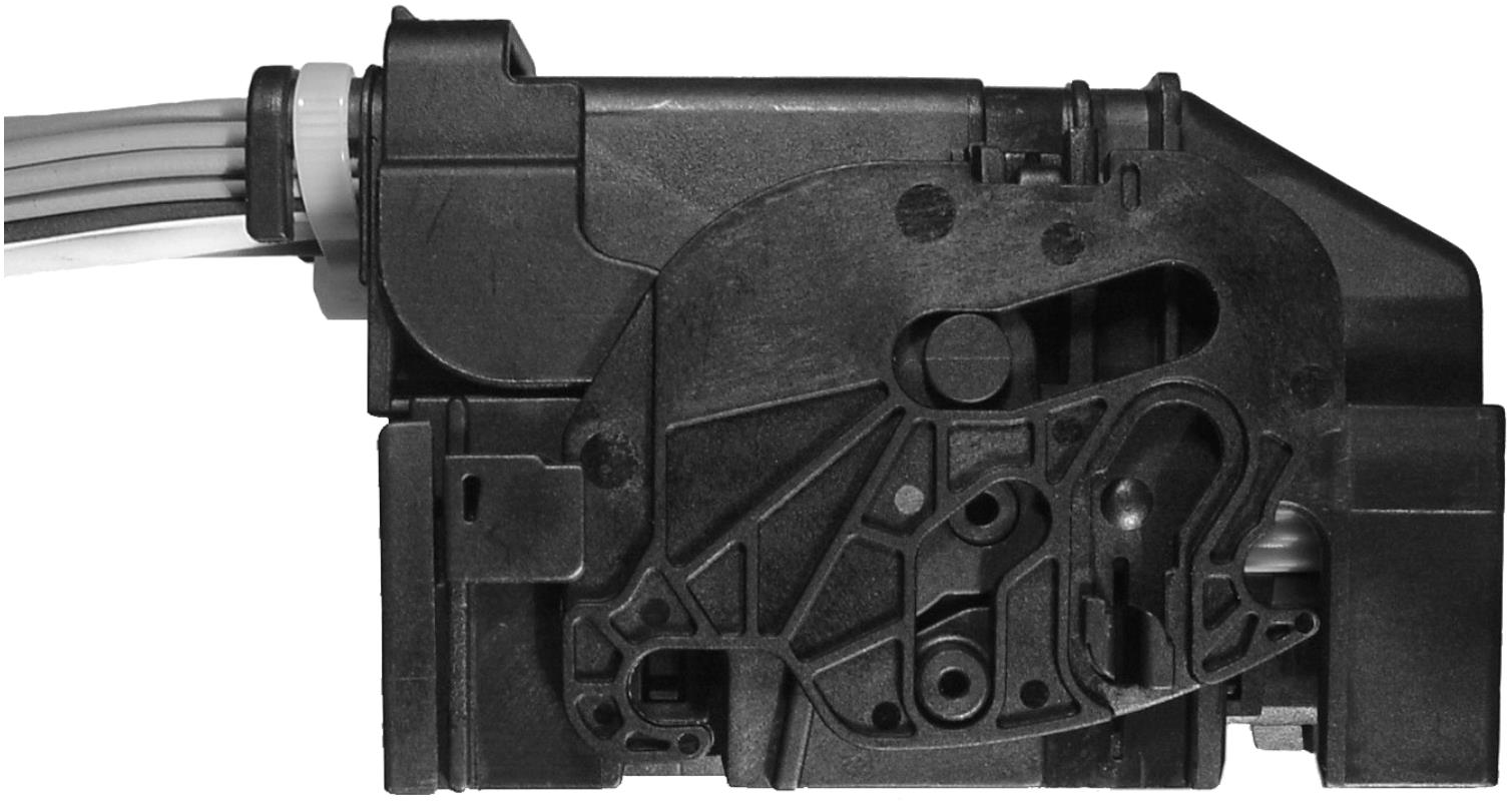
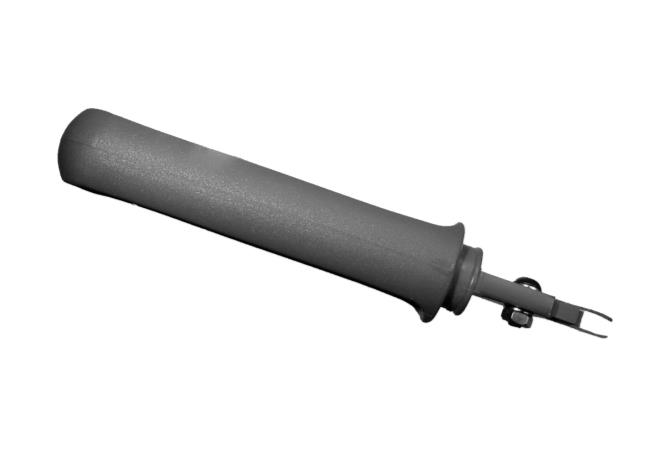
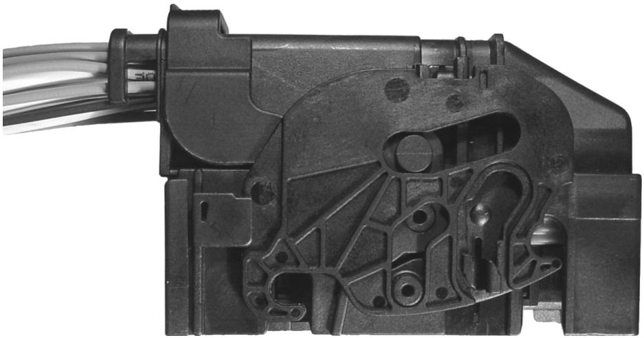
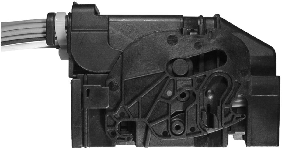
Fig. 1: 26-way connector
Ó Robert Bosch GmbH reserves all rights including industrial property rights. We reserve all rights of disposal, such as copying and passing on to third parties.
Number: Page: Date:


![]()
Assembly Instruction Y 928 F00 116-E 3 (19) 18.02.2003
|
GS-CP/ENG2 26-way connector |
Author: Püttner |
Phone extension: 2785 |
CONTENTS
1 SCOPE OF INSTRUCTIONS……………………………………………………………………………. 4
2 PARTS LIST ………………………………………………………………………………………………….. 4
3 GENERAL INSTRUCTIONS…………………………………………………………………………….. 4
4 FITTING THE TERMINALS ……………………………………………………………………………… 5
5 DISASSEMBLING THE TERMINALS ……………………………………………………………….. 9
6 INSERTING THE EQUIPPED CONTACT HOUSING IN THE COVER………………….. 11
7 REMOVING THE CONTACT HOUSING FROM THE COVER…………………………….. 13
8 FASTENING CABLES TO THE CONNECTOR, STRAIN RELIEF……………………….. 15
9 PLUGGING IN THE CONNECTOR …………………………………………………………………. 16
10 UNPLUGGING THE CONNECTOR ………………………………………………………………… 17
11 APPENDIX: DEMONSTRATION PICTURES FOR THE CONNECTING PROCESS. 18
Ó Robert Bosch GmbH reserves all rights including industrial property rights. We reserve all rights of disposal, such as copying and passing on to third parties.
Number: Page: Date:


![]()


Assembly Instruction Y 928 F00 116-E 4 (19) 18.02.2003
|
GS-CP/ENG2 26-way connector |
Author: Püttner |
Phone extension: 2785 |
1 SCOPE OF INSTRUCTIONS
These instructions are valid for:
· 26-way connector with terminals BMK 0.6 and MCP 2.8
2 PARTS LIST
Variant with cable exit on the left:
Item Designation Item number Comments
1 Cover premounted, cable exit on left,
code 1 1 928 404 410 2.1 Contact housing premounted, cable exit
on left, without protective cap 1 928 404 406 Use either item
2.2 Contact housing premounted, cable exit
2.1 or item 2.2
on left, with protective cap 1 928 404 408
Variant with cable exit on the right:
Item Designation Item number Comments
1 Cover premounted, cable exit on right,
code 1 1 928 404 494 2.1 Contact housing premounted, cable exit
on right, without protective cap 1 928 404 491 Use either item
2.2 Contact housing premounted, cable exit
2.1 or item 2.2
on right, with protective cap 1 928 404 492
Variant with cable exit on the top:
Item Designation Item number Comments
1 Cover premounted, cable exit on the up-
per side t, code 1 1 928 404 797 2.1 Contact housing premounted, cable exit
on left, without protective cap 1 928 404 406
Use either item
2.2 Contact housing premounted, cable exit
2.1 or item 2.2
on left, with protective cap 1 928 404 408
3 GENERAL INSTRUCTIONS
· Damaged parts must not be mounted and have to be separated.· The connector and its individual parts must not be exposed to dirt or damaged.· Total sealing inside the cover with foam or similar material is not permitted.· The locking lever of the fully assembled connector must be closed during transport.· Additional instructions and devices:
– Design and assembly information of wiring harness Y 280 F70 004- Final check instruction Y 928 P00 262
Ó Robert Bosch GmbH reserves all rights including industrial property rights. We reserve all rights of disposal, such as copying and passing on to third parties.
Number: Page: Date:


![]()
Assembly Instruction Y 928 F00 116-E 5 (19) 18.02.2003
|
GS-CP/ENG2 26-way connector |
Author: Püttner |
Phone extension: 2785 |
4 FITTING THE TERMINALS
The following instructions apply equally to all variants of cable exit.
· In versions with a protective cap on the contact housing, remove the cap by pulling at
the tabs on the side.
Fig. 2: 26-way contact housing, removing the protective cap
· Check that the secondary locking mechanism of the contact housing is open. If the secondary locking mechanism is closed, open it at the tip in direction “1” with the oper- ating tool 1 928 H00 009 or a screwdriver or similar. The tip of the secondary locking must not be in line with the contour of the contact housing.
Fig. 3: 26-way contact housing, opening of secondary locking mechanism
· With BMK 0.6 terminals, only use signal leads which have been produced in accor-
dance with Bosch processing specification Y 928 V03 000.
With MCP 2.8 terminals, only use power leads which have been produced in accor-dance with AMP processing specification 114-18148-1.
Ó Robert Bosch GmbH reserves all rights including industrial property rights. We reserve all rights of disposal, such as copying and passing on to third parties.
Number: Page: Date:


![]()
![]()
Assembly Instruction Y 928 F00 116-E 6 (19) 18.02.2003
|
GS-CP/ENG2 26-way connector |
Author: Püttner |
Phone extension: 2785 |
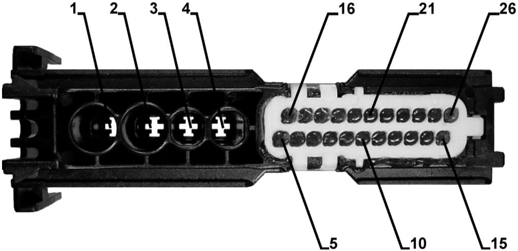
· Insert the prepared leads. Observe the cavity numbering.
Fig. 4: 26-way contact housing, cavity numbering
· Align the contours of the terminal with the cutouts in the cavity. Bear in mind that the
terminal may also be fitted turned 180°.
Fig. 5: BMK 0.6 terminal correctly aligned Fig. 6: MCP 2.8 terminal correctly aligned
· Push the terminal into the cavity until it snaps into place. The crimp must no longer be
visible.
Fig. 7: 26-way contact housing, equipping with terminals
Ó Robert Bosch GmbH reserves all rights including industrial property rights. We reserve all rights of disposal, such as copying and passing on to third parties.
Number: Page: Date:


![]()
Assembly Instruction Y 928 F00 116-E 7 (19) 18.02.2003
|
GS-CP/ENG2 26-way connector |
Author: Püttner |
Phone extension: 2785 |
· Check that each terminal is correctly locked in place by gently pulling the cable (pull
back-test).
Fig. 8: 26-way contact housing, checking the primary locking mechanism
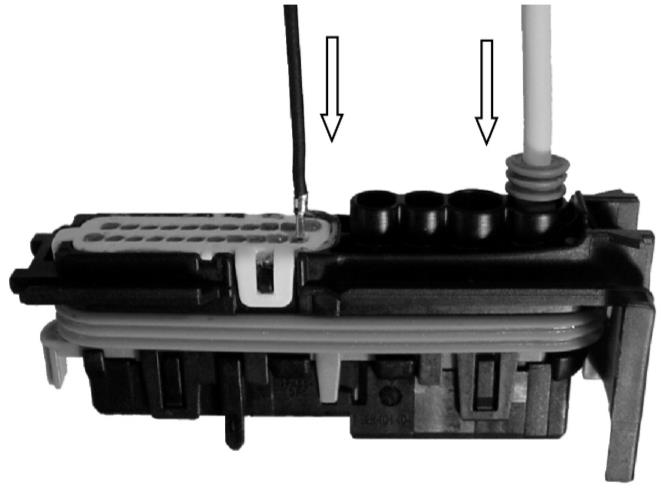
· Not used BMK 0.6 cavities must not be extra sealed.
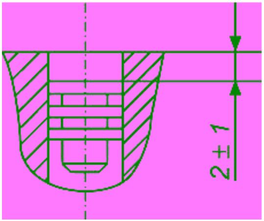
· Not used MCP 2.8 cavities must be sealed with dummy plugs. These plugs must be seated 2 ± 1mm deep in the contact cavities.
Abb. 9: Position of dummy plug
Ó Robert Bosch GmbH reserves all rights including industrial property rights. We reserve all rights of disposal, such as copying and passing on to third parties.
Number: Page: Date:


![]()
![]()
Assembly Instruction Y 928 F00 116-E 8 (19) 18.02.2003
|
GS-CP/ENG2 26-way connector |
Author: Püttner |
Phone extension: 2785 |
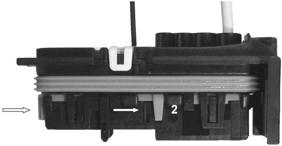
· Close the secondary locking mechanism by pressing at the tip in direction “2”. This could be done with the operating tool 1 928 H00 009 or a screwdriver or similar. The secondary locking mechanism can be felt to snap into place. It is correctly closed if its tip is in line with the contact housing.
Fig. 10: 26-way contact housing, closing of secondary locking mechanism
Note:
If there is increased resistance when closing the secondary locking mechanism, then anincorrectly seated terminal has been detected. Open the secondary locking mechanismcompletely and check then if all terminals are in full down position. Close the secondarylocking mechanism again as described above.
Ó Robert Bosch GmbH reserves all rights including industrial property rights. We reserve all rights of disposal, such as copying and passing on to third parties.
Number: Page: Date:


![]()
![]()

Assembly Instruction Y 928 F00 116-E 9 (19) 18.02.2003
|
GS-CP/ENG2 26-way connector |
Author: Püttner |
Phone extension: 2785 |
5 DISASSEMBLING THE TERMINALS
The following instructions apply equally to all variants of cable exit.
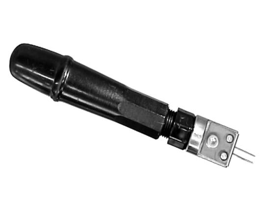
· For BMK 0.6 terminals, use Bosch extracting tool 1 928 498 106.
For MCP 2.8 terminals, use AMP extracting tool 929 039-1.
Fig. 11: BMK 0.6 Extracting tool, 1 928 498 106 Fig. 12: MCP 2.8 Extracting tool, 929 039-1
· For further information of using the BMK-extraction tool see leaflett Y 928 F00 070,
delivered with the extraction tool.
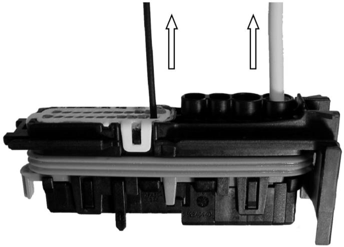
· Open the secondary locking mechanism at the tip in direction “1” with the operating tool 1 928 H00 009 or a screwdriver or similar. The secondary locking mechanism can be felt to snap open. The tip of the secondary locking must not be in line with the contour of the contact housing.
Fig. 13: 26-way contact housing, opening of secondary locking mechanism
Ó Robert Bosch GmbH reserves all rights including industrial property rights. We reserve all rights of disposal, such as copying and passing on to third parties.
Number: Page: Date:


![]()
![]()
![]()
![]()
Assembly Instruction Y 928 F00 116-E 10 (19) 18.02.2003
|
GS-CP/ENG2 26-way connector |
Author: Püttner |
Phone extension: 2785 |
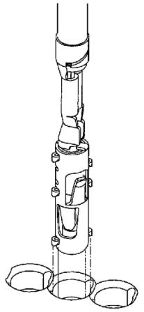
· Press the terminal forwards slightly by pushing the cable.
· Insert the extracting tool forwards into the extraction holes as far as the stop.
Fig. 14: 26-way contact housing, removal of BMK 0.6 terminal Fig. 15: 26-way contact housing, removal of MCP 2.8 terminal
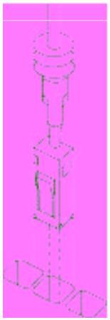
· Pull out the terminal with cable.
Fig. 16: 26-way contact housing, removal of BMK 0.6 terminal Fig. 17: 26-way contact housing, removal of MCP 2.8 terminal
Note:
Before reinstalling a terminal, check it for damages (for example, bent primary lockingspring, damaged contours) and replace if necessary.
MCP 2.8 terminals may be removed any number of times.
BMK 0.6 terminals may only be fit 3 times in and 2 times out in the same cavity.
Ó Robert Bosch GmbH reserves all rights including industrial property rights. We reserve all rights of disposal, such as copying and passing on to third parties.
Number: Page: Date:


![]()
Assembly Instruction Y 928 F00 116-E 11 (19) 18.02.2003
|
GS-CP/ENG2 26-way connector |
Author: Püttner |
Phone extension: 2785 |
6 INSERTING THE EQUIPPED CONTACT HOUSING IN THE COVER
The following instructions apply equally to all variants of cable exit.
Once the contact housing has been properly equipped and the secondary locking mecha-nism correctly closed, the contact housing can be inserted in the cover.
· Check whether the locking lever of the cover is closed. If not, close it.
Fig. 18: 26-way cover, locking lever closed
· Hold the leads in the direction of the cable exit, so that the contact housing can be in-
serted into the cover without damaging the leads.
· Position the contact housing next to the guide elements in the cover and push into the cover. Ensure that the contact housing clicks into place in the cover. Make sure not to squeeze any leads.
Fig. 19: Inserting the equipped contact housing in the cover
Ó Robert Bosch GmbH reserves all rights including industrial property rights. We reserve all rights of disposal, such as copying and passing on to third parties.
Number: Page: Date:


![]()
Assembly Instruction Y 928 F00 116-E 12 (19) 18.02.2003
|
GS-CP/ENG2 26-way connector |
Author: Püttner |
Phone extension: 2785 |
· Finally, check that both sides of the contact housing have correctly engaged in the
cover.
Fig. 20: Checking of engaged contact housing in the cover
Ó Robert Bosch GmbH reserves all rights including industrial property rights. We reserve all rights of disposal, such as copying and passing on to third parties.
Number: Page: Date:


![]()
Assembly Instruction Y 928 F00 116-E 13 (19) 18.02.2003
|
GS-CP/ENG2 26-way connector |
Author: Püttner |
Phone extension: 2785 |
7 REMOVING THE CONTACT HOUSING FROM THE COVER
The following instructions apply equally to all variants of cable exit.
· Check whether the locking lever of the cover is closed. If not, close it.
Fig. 21: 26-way connector, locking lever closed
· Using a small screwdriver or similar, release the catches on both sides (A). At the same time, press the contact housing slightly in the direction of the cable exit (B). Pull- ing on the harness and at the plate (C) is not allowed.
A
C
B
Fig. 22: Releasing the catch holding the contact housing in the cover
Ó Robert Bosch GmbH reserves all rights including industrial property rights. We reserve all rights of disposal, such as copying and passing on to third parties.
Number: Page: Date:


![]()
![]()
Assembly Instruction Y 928 F00 116-E 14 (19) 18.02.2003
|
GS-CP/ENG2 26-way connector |
Author: Püttner |
Phone extension: 2785 |
· Pull the contact housing at (B) out of the cover in the direction of the cable exit. Pulling
on the harness and at the plate (A) is not allowed.
B
A
Fig. 23: Removing the contact housing from the cover
Note:
If you meet with high resistance when removing the contact housing, check once againthat the catch is released and repeat the releasing process if necessary.
When the contact housing has been removed from the cover, disassembly of the connec-tor is complete. The closing mechanism of the cover is not intended to be removed.
Ó Robert Bosch GmbH reserves all rights including industrial property rights. We reserve all rights of disposal, such as copying and passing on to third parties.
Number: Page: Date:


![]()
Assembly Instruction Y 928 F00 116-E 15 (19) 18.02.2003
|
GS-CP/ENG2 26-way connector |
Author: Püttner |
Phone extension: 2785 |
8 FASTENING CABLES TO THE CONNECTOR, STRAIN RELIEF
The following instructions apply equally to all variants of cable exit.
· Carefully bend the lead bundle in the direction of the cable exit.
· Secure the lead bundle to the cover using cable ties. Make sure to route the leads so that the lenght between the contact cavity and the strain relief is as long and as flexible as possible. Make sure the leads are guided in a maximum loop to prevent bending of terminals in the cavity.
· The lock of the cable tie has to be assembled at the open side of the handle cover. Otherwise the lever can’t be closed correctly, especially at the housing with cable exit on the top.
Fig. 24: 26-way connector, mounted cable tie
Ó Robert Bosch GmbH reserves all rights including industrial property rights. We reserve all rights of disposal, such as copying and passing on to third parties.
Number: Page: Date:


![]()
Assembly Instruction Y 928 F00 116-E 16 (19) 18.02.2003
|
GS-CP/ENG2 26-way connector |
Author: Püttner |
Phone extension: 2785 |
9 PLUGGING IN THE CONNECTOR
The following instructions apply equally to all variants of cable exit.
· Check whether the locking lever is open. If not, open it completely.
Fig. 25: 26-way connector, locking lever opened
· Position the connector on the terminal strip in the correct position, and push in as far as
the stop.
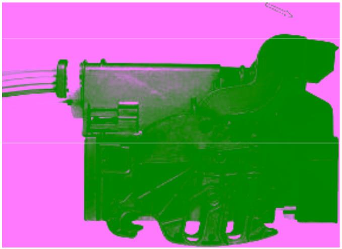
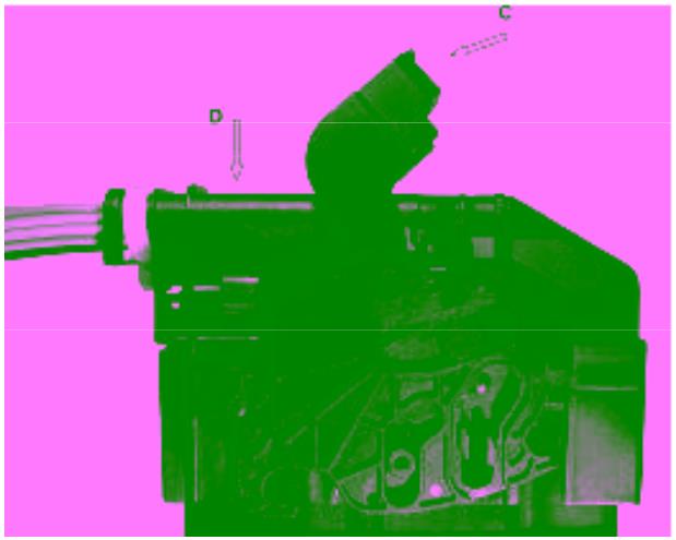
· Close the locking lever (C) whilst pressing the connector against the terminal strip (D).
Snap the locking lever into place. It must be in line with the top of the cover.
Fig. 26: Plugging in the 26-way connector
· Ensure that the connector – especially the locking claws – are correctly seated.
Ó Robert Bosch GmbH reserves all rights including industrial property rights. We reserve all rights of disposal, such as copying and passing on to third parties.
Number: Page: Date:


![]()
Assembly Instruction Y 928 F00 116-E 17 (19) 18.02.2003
|
GS-CP/ENG2 26-way connector |
Author: Püttner |
Phone extension: 2785 |
10 UNPLUGGING THE CONNECTOR
The following instructions apply equally to all variants of cable exit.
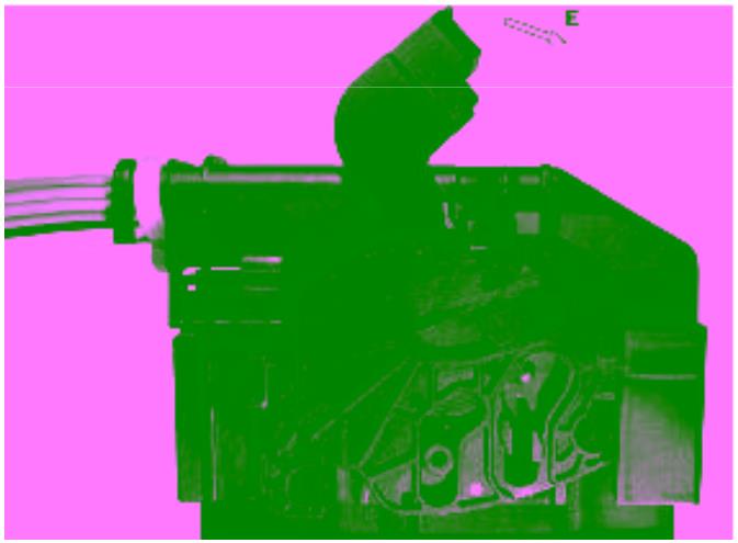
· Open the locking lever as far as the stop (E). You may need to make use of a screw-
driver to assist you in releasing the locking lever.
Fig. 27: Unplugging the 26-way connector
· Remove the connector from the terminal strip.
· Close the locking lever. The lever must be in line with the top of the cover.
Fig. 28: 26-way connector, locking lever closed
Ó Robert Bosch GmbH reserves all rights including industrial property rights. We reserve all rights of disposal, such as copying and passing on to third parties.
Number: Page: Date:


![]()
Assembly Instruction Y 928 F00 116-E 18 (19) 18.02.2003
|
GS-CP/ENG2 26-way connector |
Author: Püttner |
Phone extension: 2785 |
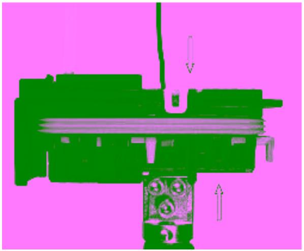
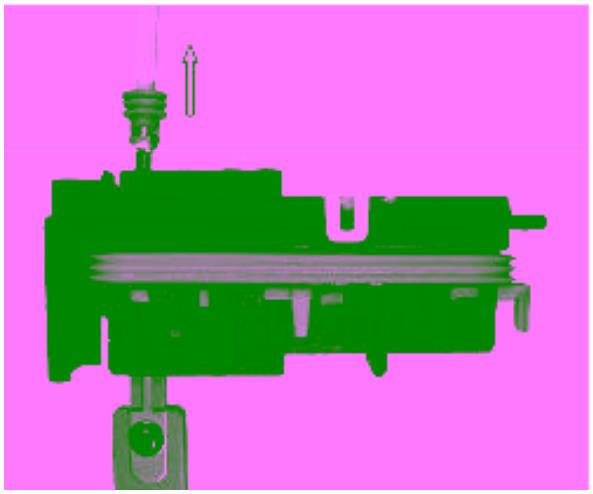
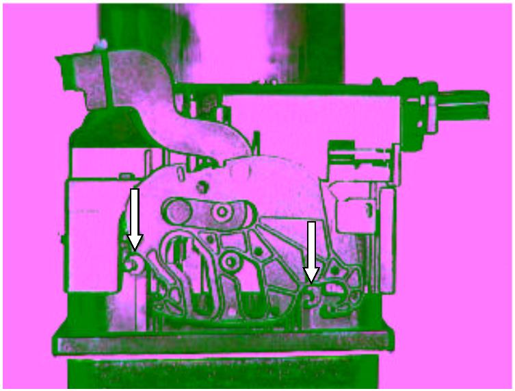
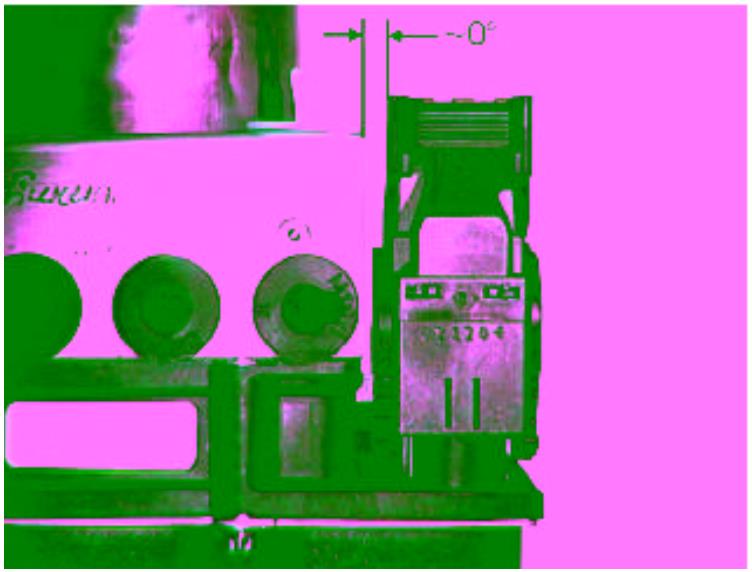
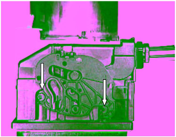
11 APPENDIX: DEMONSTRATION PICTURES FOR THE CONNECTING PRO- CESS
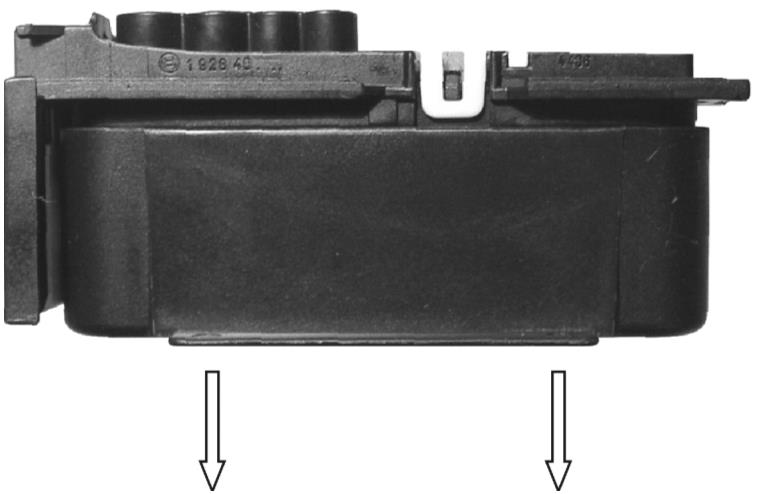
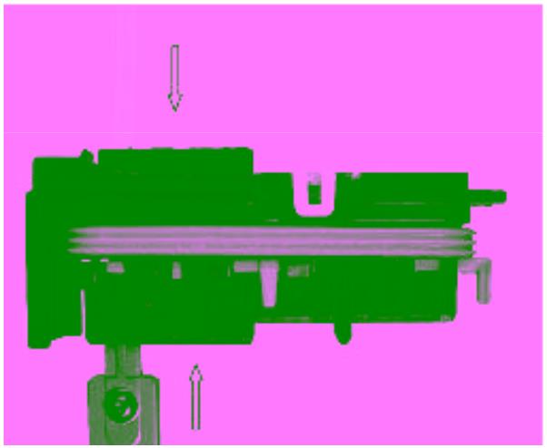
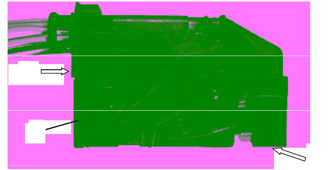
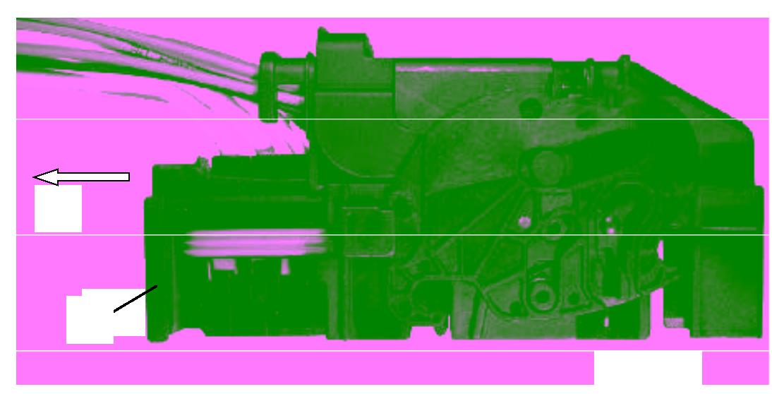
Correct: The connector is placed horizontal and as far as the stop (see arrows)
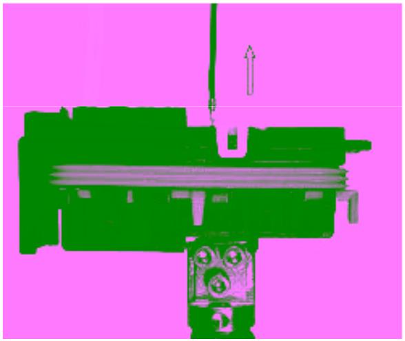
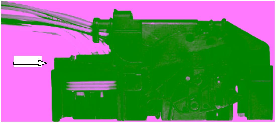
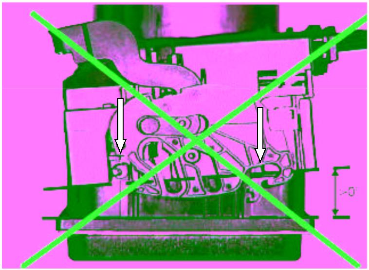
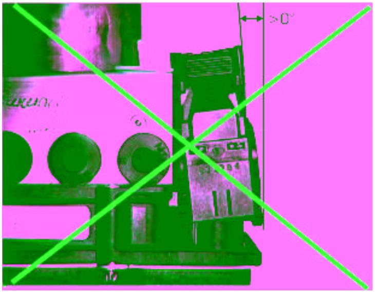
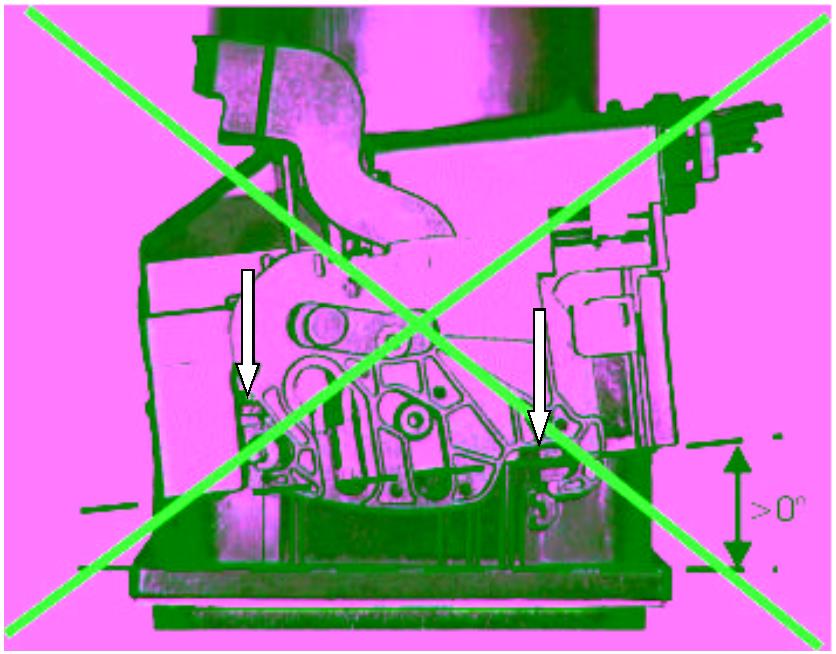
Wrong: The connector is placed with angle and not as far as the stop as well (see arrows)
Ó Robert Bosch GmbH reserves all rights including industrial property rights. We reserve all rights of disposal, such as copying and passing on to third parties.
Number: Page: Date:


![]()
Assembly Instruction Y 928 F00 116-E 19 (19) 18.02.2003
|
GS-CP/ENG2 26-way connector |
Author: Püttner |
Phone extension: 2785 |
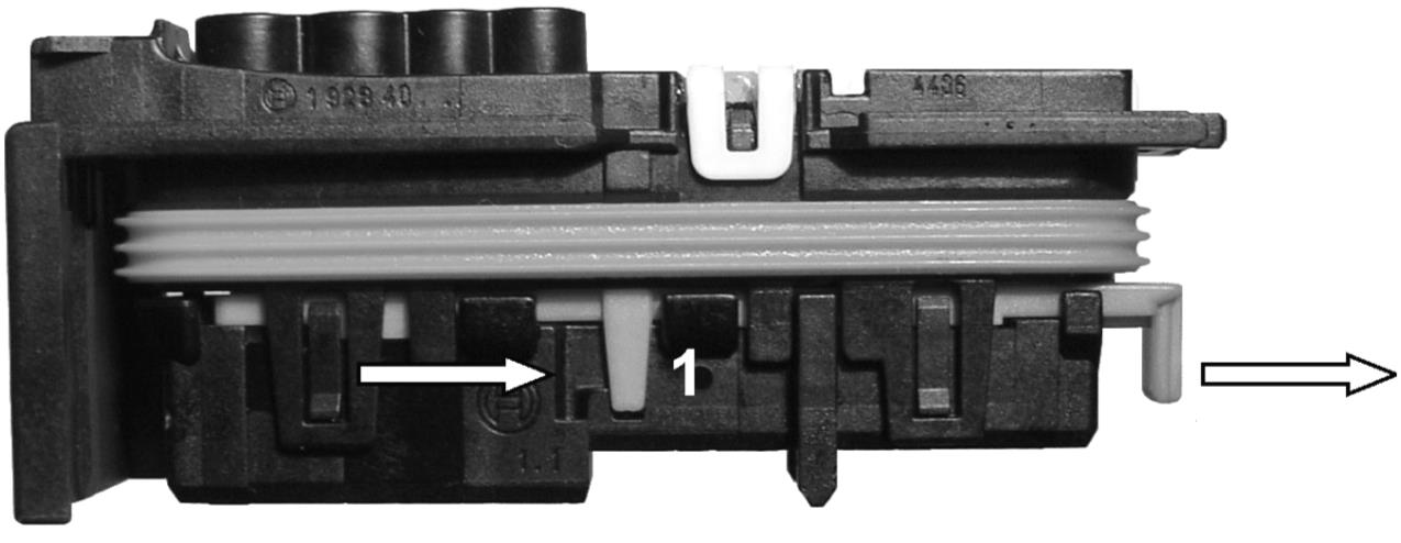
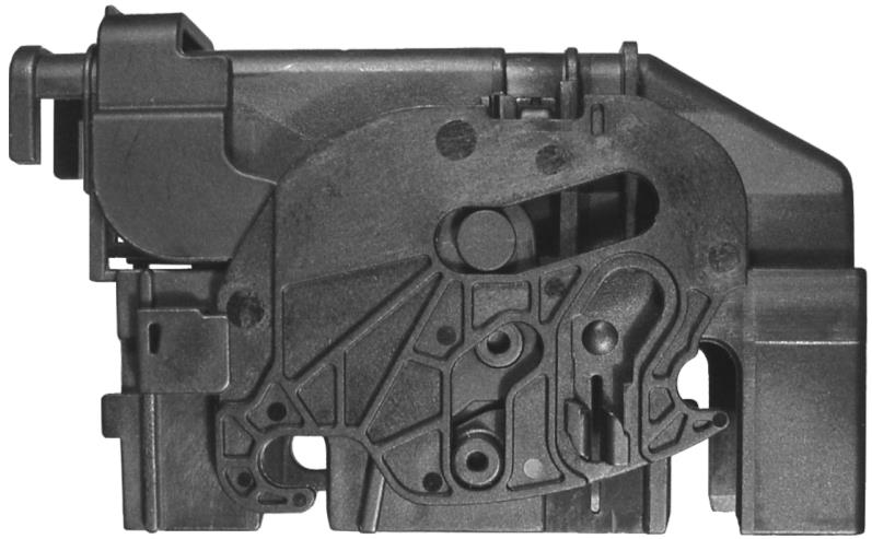
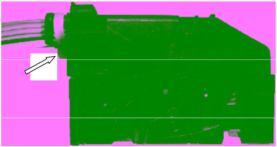
Correct: The connector is mated properly
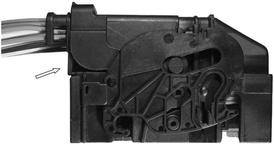
Wrong: The connector is mated with angle and incompletely as well (see arrows)
Ó Robert Bosch GmbH reserves all rights including industrial property rights. We reserve all rights of disposal, such as copying and passing on to third parties.
Y928F00116-ENW06B00